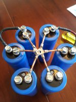

If you go with a large copper between the 6 caps the resistance between each would be very small . This also give you an area to connect the other ground to . The resistance of a sheet of 2 mm copper would be hard for most to measure point to point at any where near the current it will see.
I don't recommend a "star" for multiple smoothing capacitors.
I much prefer taking the input at one end of the string and taking the output from the other end of the string. The return for each flow string should follow as closely as possible.
The big loop in each of the R & L halves emits emi. And the Star in mo way helps to reduce the size of those loops.
I much prefer taking the input at one end of the string and taking the output from the other end of the string. The return for each flow string should follow as closely as possible.
The big loop in each of the R & L halves emits emi. And the Star in mo way helps to reduce the size of those loops.
I don't recommend a "star" for multiple smoothing capacitors.
I much prefer taking the input in at one end of the string and taking the output from the other end of the string. The return route for each flow string should follow as closely as possible, to minimise loop area.
The big loop in each of the R & L halves emits emi. And the Star in no way helps to reduce the size of those loops.
Posted to correct errors in post29.
I am not inclined to agree.
I think the charging pulses into the first pair of smoothing caps must be resolved at the the first pair of zero volt connections.
The smaller value but longer charging pulses in the second pair should be resolved at the second pair zero volt connections.
The hopefully very small and almost continuous charging pulses of the third pair should be resolved at the third pair zero volt connections.
This cleanest zero volt connection is then taken to the Main Audio Ground.
But back to the input to that smoothing bank.
The two AC and the Centre tap must arrive as a close coupled triplet. This triplet should be very short in length and very low in loop area. i.e. the transformer secondary + rectifier + 1st pair smoothing MUST be VERY compact.
Then arrange the cabling to minimise loop area all the way from mains input right through to speaker output terminals.
Andrew,
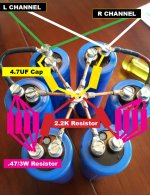
I believe this is what you are talking about.
Seems like Zen is trying to minimize potential grounding issues, you are trying to minimize potential RFI issues. Both would probably work...I have not decided what to do yet. But resistors will arrive this week so I have couple days to figure it out.
I believe this is what you are talking about.
Seems like Zen is trying to minimize potential grounding issues, you are trying to minimize potential RFI issues. Both would probably work...I have not decided what to do yet. But resistors will arrive this week so I have couple days to figure it out.
Attachments
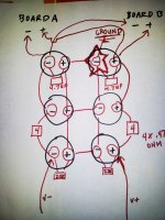
you have shown double connections from Zero volts1 (at the bottom) to Zero volts2 and again double connections from Zero volts2 to Zero volts3.
You need to add a centre tap connection to the bottom zero volts1.
You need to add a zero volts connection to each amplifier channel. This connection must go to the MAG. The MAG must be located to minimise hum.
Although your diagram is "opened up" to make it readable, I recommend that all the "open" loops be closed down such that every flow and return pair are close coupled.
Last edited:
- Status
- This old topic is closed. If you want to reopen this topic, contact a moderator using the "Report Post" button.
- Home
- Amplifiers
- Pass Labs
- Jim's Audio F5 power supply board