Only if you increase the amt of class-a bias ....
Do you prefer more devices at lower current than fewer devices at higher current?
Max wire length (FE --> power boards)
What's the max length of the wires from the front end board to the power board?
Here's why I am asking: I am planning to build a F5T monoblock with four power boards, one board on each side/front/rear (yes, heatsinks on all four sides). Since the transformer will be somewhere in the center of the chassis, I'd think it would be better to keep the front end (FE) board away from the center. I thought of mounting the FE board to the rear heatsink, and then have wires going from there to the four power boards. The wires from FE on the rear to the power board on the front will end up being 40 or 50 cm long or so.
What do you guys think?
Each output device needs a 3wire connection. I have asked, but got no answer to how we run these wires.
Twisting all three together seems wrong to me, but might be the best way.
Twisting the two high current wires together could be better and leaving the low current alongside, or spaced apart?
Or all three spaced apart?
I don't know.
Once that is answered maybe we could work out what it is that could cause an instability problem and then define the maximum distance in terms of parasitics/inch.
Each output device needs a 3wire connection. I have asked, but got no answer to how we run these wires.
Twisting all three together seems wrong to me, but might be the best way.
Twisting the two high current wires together could be better and leaving the low current alongside, or spaced apart?
Or all three spaced apart?
I don't know.
Once that is answered maybe we could work out what it is that could cause an instability problem and then define the maximum distance in terms of parasitics/inch.
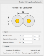
I think that twisted wires will minimize the pickup of hum, because the loop area between the wires will be small. Or is the resistance/impedance seen by the wires (on the FE board or the power boards) too small for efficient hum pickup?
Twisted pairs (or wires that are close to each other) may also add some inductance and capacitance. According to some online calculator tool, the capacitance of a 50cm long twisted pair would be in the range of 30 pF, and the inductance in the range of 200 nH or so (see attached screenshot; depends a lot on the thickness, distance and insulation of the wires).
(How) Would that affect the performance of the circuit?
Attachments
Last edited:
Thanks for this. What about the third wire? Plain? Shielded? Twisted with a grounded wire?twisting the 2 high current wires and run them strait to the PSU. they don't need to run through the FE board.
What's a reasonable max length for all these wires?
Gesendet von meinem D5503 mit Tapatalk

%FT question
Hey Guys
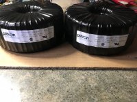
My transformers finally arrived today so I am ready to start wiring everything up. I just need a matched pair of JFETS from the DIY store when they become available.
My question is whether or not I need one speaker protection board(from the DIY shop) for each channel. I am already going to use one inrush board per channel as I am using a 1000VA transformer and 264,000uf for each channel. Does it make sense to run two speaker protection boards or will one suffice. This is a single chassis dual mono build.
Hey Guys
My transformers finally arrived today so I am ready to start wiring everything up. I just need a matched pair of JFETS from the DIY store when they become available.
My question is whether or not I need one speaker protection board(from the DIY shop) for each channel. I am already going to use one inrush board per channel as I am using a 1000VA transformer and 264,000uf for each channel. Does it make sense to run two speaker protection boards or will one suffice. This is a single chassis dual mono build.
Attachments
Hey Guys
My transformers finally arrived today so I am ready to start wiring everything up. I just need a matched pair of JFETS from the DIY store when they become available.
My question is whether or not I need one speaker protection board(from the DIY shop) for each channel. I am already going to use one inrush board per channel as I am using a 1000VA transformer and 264,000uf for each channel. Does it make sense to run two speaker protection boards or will one suffice. This is a single chassis dual mono build.
If you want to stay double mono.... yes, you'll need 2 protection boards - 1 per channel
F5 Turbo V2 build planning
Hello,
I'm presently planning to build the F5T V2.
I have selected a power transformer from Toroidy (Polish company) having 1kVA rating.
The Pass schematics claims for 2x24Vac secondary voltage, would it be a pain to have 2x25 or 2x26 Vac voltage (+- 35Vdc or +-37 Vdc no load)?
Also, since I live in Italy and have easy accessibility to HIFI2000 enclosures, I selected the 5U 500mm depth one (available in Italy). This chassis has 4 heat sinks (250mm x 210mm x 40mm each)
the heat dissipation is a little increased respect to the 400mm depth and maybe a little higher bias could be achieved.
Increasing the supply voltage do you suggest to also fit the cascode circuitry?
Concerning the PSU, from the Pass article, the PSU schematic has a thermostat 75°C in series with the primary winding of the transformer. This thermostat should be fitted on the heat sink?
thanks in advance
kind regards
Diego
I would cascode the jfets at that voltage.
My f5 v2 with 24v transformer (31v rails) can bias to 1.8 amps in the 5u 400mm chassis. Heat sink temps are 50-53c. You may be able to bias more but the higher rail voltage will make more heat.
Usually pass has the thermal cut off switch standing in free air around the cap bank. Problem with it attached to one sink is one channel may overheat without the other. Also, the switch is on the ac line, before the transformer.
Last edited:
What value of parts would be used for the cascode? Never have been clear on how these parts are calculated.....
Russellc
railvoltage/(R25+R27)xR27 = cascode voltage. (partnumbers from F5 turbo v3 schematic from the turbo article).
ex: 50Vdc rails. 50/(10+4.75)x4.75=16.1Vdc.
And do the same for R26/R28.
Last edited:
I am more than halfway through my first F5 turbo build and I’ve run into a question I can’t find an answer for.
On the N and P channel board and on the front end board, are the 100 uF electrolytic caps supposed to be non-polarized or polarized? I’m asking about
C1x on the P channel
C2x on the N channel
C1 and C2 on the front end boards
On the N and P channel board and on the front end board, are the 100 uF electrolytic caps supposed to be non-polarized or polarized? I’m asking about
C1x on the P channel
C2x on the N channel
C1 and C2 on the front end boards
Last edited:
- Home
- Amplifiers
- Pass Labs
- Building an F5 Turbo v2 (in-Progress)