The output graph in post 39 shows with the 'locus dotted line' actually the transfer graph 'seen' from the input. Even more, the ohmic region respons with reciprocal law to input and output. It is the inverse of the output graph of a triode tube.
Indeed as said by PRR: the gate current never reaches zero or it would be incapable to cut off in the first place!
Indeed as said by PRR: the gate current never reaches zero or it would be incapable to cut off in the first place!
Hello,
I have waited a couple of days; no one else has jumped in.
Join in, shine some more light, if you will. Vp and Vgs(off) still seem to be hopelessly balled up, confused.
Some texts and authors say that Vp and Vgs(off) are two names for the same thing. That thing being a gate voltage negative enough in value to shut off the Drain current to some specified near zero value. For the PF5102 that value is 1uV, this is just an example.
True, we are not going to operate our circuits at near zero current. That does not mean that knowing the value of Vgs(off) is useless. Vgs(off) is a Raito number that can be used in a SPICE model for example.
At the other end of the scale at or near Idss drainage current there is the onset of pinching. Gate voltage is at 0.00V and Drain voltage is increasing. As drain voltages increases so does JFET channel resistance, Idss remains constant, this is saturation.
Thanks DT
... Vp and Vgs(off) are two names for the same thing. That thing being a gate voltage negative enough in value to shut off the Drain current to some specified near zero value. For the PF5102 that value is 1uV...
"1uV" is not a current.
The number I see on the datasheet: VGS(off) Gate-Source Cutoff Voltage VDS = 15V, ID = 1.0nA
http://rtellason.com/transdata/pf5102.pdf
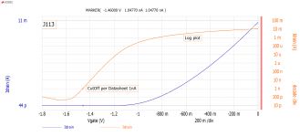
Plotting a *SPICE* model on semi-log paper, we get the idea that the Id drop-off is VERY sudden near Vp, and it may not be TOO critical what current we define as "cut off".
2N3819 and a model I found for NF5102.
Yes, SPICE models are NOT carefully checked for very-low currents like this. It predicts the simple math observed from "normal current", and rarely tries to include the low-current effects.
2N3819 and a model I found for NF5102.
Yes, SPICE models are NOT carefully checked for very-low currents like this. It predicts the simple math observed from "normal current", and rarely tries to include the low-current effects.
Attachments
A big part of experience in electronics is not wasting time and energy on fruitless directions and details. I think the experienced commenters have given their advice. Do you want to make an amplifier or write a paper on JFET curves? If you do not have a amplifier in mind, then sorting by Ids is useful. If you have an amplifier built, put a socket in place of the FETs and fine tune the Ids pairs for amplifier performance, and why doesn't matter.
Hello,
PRR, 1uV was a typo and you are correct that the PF5102 datasheet does call out 1nA Drain current at a Drain voltage of 15V. Thanks for posting the SPICE model plots. Back in post 38 there are plots of measurements of a PF5102 on the bench plus a PDF of the data points; Gate Voltage vs Drain Current. The Drain Current gradually tapers off with decreasing Gate voltage. I am thinking that I will start the modeling with CutOff := 1uA. One 1nA is way out on the tail of the measured curve. Looks to me that Scott is right; the text book model and subthreshold measurements do not line up very well.
I am still intending to do the Excel curve fitting and Solver approach with the data in the PDF attached in post 38.
steveu, you and I have completely different ideas about wasting time, some people do crosswords. I did fabricate a nice little decade box on a perf board with DIP switches and ¼ watt resistors. It works very well selecting bias resistors and finding the sweet spot for distortion.
Thanks DT
#42> Pinch-Off is the point that separates the ohmic part of the curve from the saturated part of the curve.
That is another "pinchoff".
The two values would be the same in an Ideal JFET. Except that the top of the knee is ill-defined. Do you take it at 1% droop, 10% droop, or what?
The gate-source turn-off voltage is better defined because current drops quite suddently (on log plot, not on your lin-plot).
The drain-gate saturation point is mostly useful to pencil-sketch a loadline. And real JFETs with graded/gradual junctions give indistinct saturation.
#42> Pinch-Off is the point that separates the ohmic part of the curve from the saturated part of the curve.
That is another "pinchoff".
The two values would be the same in an Ideal JFET. Except that the top of the knee is ill-defined. Do you take it at 1% droop, 10% droop, or what?
The gate-source turn-off voltage is better defined because current drops quite suddently (on log plot, not on your lin-plot).
The drain-gate saturation point is mostly useful to pencil-sketch a loadline. And real JFETs with graded/gradual junctions give indistinct saturation.
Hello,
“the top of the knee is ill-defined” is accounted for by the LAMBDA variable in the text book model.
Measurement of the CutOff voltage does not drop off nearly as suddenly as the SPICE model plots. See the attached real world measurement plot.
Thanks DT
Attachments
- Status
- This old topic is closed. If you want to reopen this topic, contact a moderator using the "Report Post" button.
- Home
- Amplifiers
- Pass Labs
- JFET Matching/Sorting