So I'm stuffing my first board and I want to clarify some values. I understand value and multiplier but still have some questions...
To check my value conversions, I'm using this online calculator.
I bet if you looked at the PCB layout you could find that trimpot's footprint and immediately know the required pin configuration. Then, knowing the layout of the pins, I bet you could pull up all of the tripmots at Mouser which match it and which are IN STOCK. Then you could filter out and discard all trimpots which have fewer than 15 turns. Then you could sort by price and pick the cheapest. Or you could sort by availability and pick the one with the greatest number of units in stock and on the shelf.
I've gathered most of the parts for my reduced version of AB100 (only ztx 450 and output transistors still waiting) I will use for VA BD 139/140 and maybe also a multiplier transistor will be BD - because it is easier to attach them to heat-sink. PSU will be double bridge ( for some extra voltage drop - and i like double bridge config). 30 000uf per rail. Snuberr cap + resistor will be soldered on transformer pads. I think i will get some 35- 36 VDC per rail from 26,26 VAC. It will be fine for BD as VA and for one pair of 250W MJ 10115/10116 darlingtons IMHO.
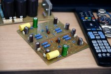
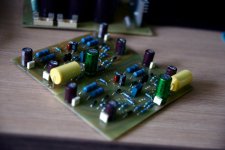
p.s. Good looking red PCB - I like them!
p.s. Good looking red PCB - I like them!
Attachments
@osscar: Thanks! I thought the red PCB’s might make this amp a little more special.Nice build so far.
Thank you,
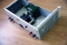
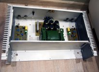
this time I try to use the salvaged parts ( transformer, enclosure, binding posts etc) .. some kind of eco friendly build
Semiconductors and other parts will be new ones - vishay resistors, ER will be two 0R47 in parallel, input cap - poly 3,3 uf, feedback cap - green muse bipolar.
Power supply unit tested - it outputs healthy + /- 37V...
It will be necessary to re-paint the scratched surfaces - maybe I'll paint it too early,,,
I try to use the existing holes in the enclosure as much as possible.How do other builders progress?
Attachments
Nice one osscar,
To others,
For AB100 builders with Mr. Pass design , I think a 19" 3U amplifier case size with 300mm + depth would be ideal for the stereo amplifier. It would have enough room for any other circuits like protect/ volume controller, etc.
e.g. dissipante 3U by DIYA
Regards
Prasi
To others,
For AB100 builders with Mr. Pass design , I think a 19" 3U amplifier case size with 300mm + depth would be ideal for the stereo amplifier. It would have enough room for any other circuits like protect/ volume controller, etc.
e.g. dissipante 3U by DIYA
Regards
Prasi
Yes Mark I did look at and measure the footprint. Looking on Mouser I'm finding everything slightly different. I'm just wondering if anyone knew immediately to save me some time. I'm sure there are many it just searching through them.
Measure the distance between center hole and other holes of the trimpot on the PCB , if its 2.54mm, then a Bourn's 3299Y would fit.
https://www.bourns.com/pdfs/3299.pdf
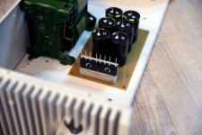
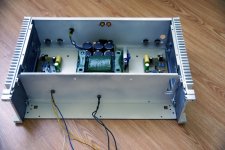
 Yes there is some addiction that even at night i think - what to do better, how to organize wires etc..
everything done - only transistors left to solder - delivery of heat-sinks is delayed, i do not want to solder transistors without them - i can miss the right height ..
Attachments
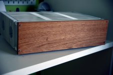
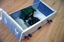
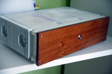
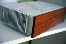
Very slow progress for me ... still waiting for LED indicators, rubber feet .... Main wires tightened- transistors screwed. Wood panel finished.
P.s. first seen ON semi BD 139/140 all-plastic housings with insulated colector.
P.s. first seen ON semi BD 139/140 all-plastic housings with insulated colector.
Attachments
- Home
- Amplifiers
- Pass Labs
- AB100 Class AB Power Amplifier