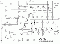
AB100 Amplifier - Micro Article by Nelson Pass
Since villagers armed with pitchforks and torches have begun camping
out my front door demanding a Class AB power amplifier, and
Whereas, I am inclined to demonstrate my goodwill in this manner and
do in fact have a 13 year old piece laying around unpublished,
I Hereby Present the AB100 Class AB Bipolar power amplifier.
Salient Specifications:
Rails: +/-50V or so
Gain: 36 dB (this was the request of the people who commissioned
this but did not want to pay for it)
Bandwidth: 5 Hz to 100 KHz (-3 dB)
Damping Factor: about 500
Maximum power: 100 Watts 8 ohms, 200 Watts 4 ohms
Slew Rate: 30 V/uS
Bias Current: about 0.08 A per channel
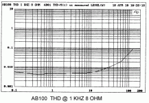
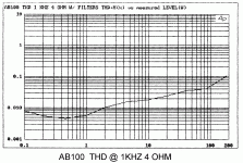
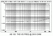
Following are several graphics. (Unfortunately I scanned them in the
distant past, so the quality is not up to my usual standards)
Let It Not Be Said: That I never did anything for you....
Attachments
Last edited:
Very cool.
Or at least less rejected heat than 100WPC class-A.


EDIT -
Ok, which of the smaller transistors need to be mounted on the main heatsinks for thermal tracking?
TIP-142 and -147 are available in TO-247 -- hooray!
What can be substituted for the 2SA1110 and 2SC2590? (If anything...)
Or at least less rejected heat than 100WPC class-A.
EDIT -
Ok, which of the smaller transistors need to be mounted on the main heatsinks for thermal tracking?
TIP-142 and -147 are available in TO-247 -- hooray!
What can be substituted for the 2SA1110 and 2SC2590? (If anything...)
Last edited:
after enough staring , everything is Aleph lookalike
I know .......

yes i know
Looking at it a bit more...
Is 100uf necessary on the input? Or is that just insurance against the rest of the world?
Does the pot adjust bias or output DC offset?
Are the neg gate diodes 4004's and the positive rail 4001's, or is that a typo? Should they all be 4004's?
Is everything, as currently drawn in the schematic, an electrical junction? Specifically, look to the right of R4.
Approx. how many VA, per channel, is required of the power transformer?
Last edited:
this one can be a nice little brout for sub/ low end. or even full range. all doh i prefer a class A or 3 for my fullrange is anyone up for a PCB layout? "hint hint" alex
and i have to send a big thank you to Nelson. who gives us all this wonderfull schematics and curcuits where would we be without you?
and ofcourse, a extra thank you for all the support and inspiration you give us
and i have to send a big thank you to Nelson. who gives us all this wonderfull schematics and curcuits
and ofcourse, a extra thank you for all the support and inspiration you give us
Last edited:
Let It Not Be Said: That I never did anything for you....

I hope no one has ever said that.
I hope no one has ever said that.
+1. nelson have done more for us DIY nuts then any other have ever done
A few quick answers.
The original design (this one) was intended for dummies with maximum
reliability and minimum adjustment and also minimum opportunity for
noises and pops. The customer wanted to put a pot and switch on the
input and use it as an integrated.
The 1n4004 (or any diode) is for current limiting - they will not get burned
out with the little current available from the front end.
The bias transistor for the output stage is best mounted where the heat is.
You will note that 1 ohm resistors for bipolar outputs is rather high. Values
on the order of 0.22 would be more appropriate (see Self) but we do get
higher reliability with 1 ohm values.
The 0 pf is provided for when oscillation occurs. I didn't see it in the sample
units.
Also note that resistors are XXX plus multiplier: 1001 is 1K.
- Home
- Amplifiers
- Pass Labs
- AB100 Class AB Power Amplifier


