Hi Jan
In the BOM, those caps are rated 50V.
Try TRX Electronics in Pretoria for hard to find components. They import from Mouser, etc.
Good luck
Christo
PS I'll send you the BOM if you send your email by PM.
In the BOM, those caps are rated 50V.
Try TRX Electronics in Pretoria for hard to find components. They import from Mouser, etc.
Good luck
Christo
PS I'll send you the BOM if you send your email by PM.
hi,
C5 and C6 should be 63V (as filter caps ) for +-50V to be on safe side
C7 and C8 can be as low as 16V. I used film cap as c7 (2uf2 or so) .for c8 i used bipolar(non-polar) el.cap- 25 or 50V because i had them.
c12 also can be 16 or 25 V or higher...across C7, C8, C12 there are now high voltage during normal conditions. Higher voltage caps are usually bigger..so its depend on PCB pad size.
Last edited:
osscar, just a last question, I will be using Prasi's layout. In the original circuit R3 were 1k, you changed it to 100R to lower the gain. I will be using 1R emitter resistors , would it be better to keep R3 at 100R ? Why did you decide to lower it initially, oscillation ? ")
Regards
Jan
Regards
Jan
Thanks osscar, much appreciated, delivery dates changed again apparently due to Corona, lets hope for the best.
DARLINGTON PNP 100V 10A 125W TO247
Stock no.:7743666
Qty:8New delivery date:
11/09/2020Choose alternativeTRANS GP BJT NPN 45V 0.1A 3-PIN TO-92
Stock no.:6711113
Qty:50New delivery date:
29/07/2020Choose alternativeDARLINGTON NPN 100V 10A 125W TO247
Stock no.:7743662
Qty:8New delivery date:
16/10/2020Choose alternative
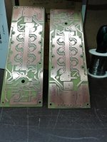
 nice diy boards!
Gooday osscar, can you please affirm, I know you used a smaller input cap and lower emitter resistors. The feedback resistor of 100R as well. What are all the changed values that you have used, info appreciated.Perhaps a schematic with all the changes would be nice !
Regards
Jan
Regards
Jan
Last edited:
- Home
- Amplifiers
- Pass Labs
- AB100 Class AB Power Amplifier