If you place the attenuator after the pre, then :
1) your pre has to output a voltage of say 20Vrms, instead of say 2Vrms, assuming your source has 2Vrms output;
2) your attenuator has to take a lot more voltage, and hence current, and hence thermal dissipation.
Can be done, if that is what you want.
Patrick
1) your pre has to output a voltage of say 20Vrms, instead of say 2Vrms, assuming your source has 2Vrms output;
2) your attenuator has to take a lot more voltage, and hence current, and hence thermal dissipation.
Can be done, if that is what you want.
Patrick
I have received a few PM's this week asking about the project.
Again thank you for your interest.
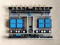
I can tell you that two examples are being beta tested since earlier this year.
This includes the complete project as you see here, with mechanical parts.
I cannot promise when it will be finished, as everyone has a day job and this is hobby.
But when it is finished, probably not before end of 2018, we'll make it available to all interested.
And yes, we have more than enough matched devices.
In the meantime, I can only ask for your patience.
I know it is taking way too long.
But we will not rush to put out projects until they have been test built thoroughly.
Patrick
Again thank you for your interest.
I can tell you that two examples are being beta tested since earlier this year.
This includes the complete project as you see here, with mechanical parts.
I cannot promise when it will be finished, as everyone has a day job and this is hobby.
But when it is finished, probably not before end of 2018, we'll make it available to all interested.
And yes, we have more than enough matched devices.
In the meantime, I can only ask for your patience.
I know it is taking way too long.
But we will not rush to put out projects until they have been test built thoroughly.
Patrick
There is life on planet F5X - pre ...
... a good oppertunity to post a question that circulates in my brain for quite a while already.
I am wondering how input common mode rejection is achieved in this design.
None of the design elements I have seen so far, but probably I missed that, provides input signal common mode rejection. And the H pad type of attenuator would make the situation even worse since only the differential voltage is attenuated but the common voltage is not. As a matter of fact the differential to common output voltage ratio drops by the attenuation factor.
So every any unsymmetrical source, be it SE RCA input or a balanced but unsymmetrical sources (a wide range if not the majority of commercial balanced sources do not provide symmetrical output signals, they provide a "hot" and a "cold" pin ) on the XLR inputs would result into an very unsymmetrical pre-amp output signal with huge common mode swing and a small ( variable by attenatuor setting) differential signal riding on it.
If this would be the case I am afraid this would be far from ideal to drive the F5X Power Amplifier which assumes a symmetrical input signals.
Markus
We had this discussion years ago here (post #186 to #190).
So I do not understand why you wish to bring it up again, as it is nothing new.
For the benefit of others, a special case of common mode input signal is a single ended input, say 1Vrms at 1kHz.
This can be considered as a differential signal of 0.5Vrms + a common mode signal of +0.5Vrms.
+Vin is the sum of the two, i.e. 1Vrms.
-Vin is the difference of the two, i.e. 0V.
The two output phases will then not be fully symmetrical, because the circuit has NFB.
But their difference is still 1Vrms x closed loop gain.
You can easily simulate this in Tina using e.g. an OPA1632 in place of the F5XP.
The F5X, and the F5XP are designed to work at their best with fully symmetrical balanced sources.
A properly implemented balanced source will have negligible common mode signal.
If you want to use single ended source with the F5XP in an optimal way, the easiest is to use a SE to balanced converter.
For example something that Chris Hornbeck has posted before :
http://www.diyaudio.com/forums/tubes-valves/189153-phase-splitter-issue-3.html#post2802454
Or just use one of the many IC's available for the job.
Or just use the F5-HA and F5 as preamp and power amp if your main source is single-ended.
Cheers,
Patrick
Last edited:
Someone asked for an update to the Beta test status.
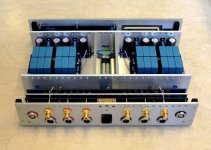
All modules have been tested in my 2nd build, as well as the Beta testers.
We have some hardware issues with the MCU control board which we do not understand.
Once that is solved, and the Beta tester have finished their build successfully, we shall release the project for all.
Unfortuinately it does not look like we'll make 2018.
Our apologies,
Patrick
For those who have been asking me in the past years for the F5X Pre project,
you can register your interest here now, for our planning purposes :
Interest for Potential GB for F5X Preamp
Thank you for your patience and support,
Patrick
you can register your interest here now, for our planning purposes :
Interest for Potential GB for F5X Preamp
Thank you for your patience and support,
Patrick
Another 6 months have gone, before I have another update to post.
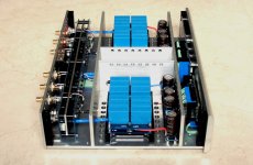
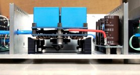
Wiring is now totally complete. Testing in the next weeks.
And then that would be it, for me at least.")
Patrick
PS This is my personal example with a few non-standard things such as Lemo connectors, etc.
.
Wiring is now totally complete. Testing in the next weeks.
And then that would be it, for me at least.
Patrick
PS This is my personal example with a few non-standard things such as Lemo connectors, etc.
.
Attachments
- Home
- Amplifiers
- Pass Labs
- The F5X Preamp