Hello,
Does anyone know if the Xono uses any higher quality resistors than the RN55D types and any esoteric capacitors? (I noticed the Pearl Phono pictures showing a Aeon cap for the output)
Thanks,
Aaron Finley
arnach5@hotmail.com
Does anyone know if the Xono uses any higher quality resistors than the RN55D types and any esoteric capacitors? (I noticed the Pearl Phono pictures showing a Aeon cap for the output)
Thanks,
Aaron Finley
arnach5@hotmail.com
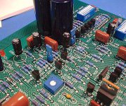
The resistors look quite ordinary if we talk industrial usage but ordinary meens very good I would say!
I like the looks of the pcb's, looks "serious".
BTW: Nelson, why have you chosen to have cross hatched groundplane? Technical reason, your software desides or is it for the looks only?
Is it possibible to take a peek sneak of the schematics? Just curious!
I like the looks of the pcb's, looks "serious".
BTW: Nelson, why have you chosen to have cross hatched groundplane? Technical reason, your software desides or is it for the looks only?
Is it possibible to take a peek sneak of the schematics? Just curious!
Here is a link: http://www.passlabs.com/aleph.htm
I had trouble to find it first time too after side has been redesigned.
I had trouble to find it first time too after side has been redesigned.
jam said:Peranders,
I believe a cross-hatched ground plane has less capacitance than a regular ground plane.
Jam
I have read somewhere that a solid groundplane ALWAYS is best in electrical terms. It's also an advantage when you make pcb's. It's good to have as much copper as possible in order to get even thickness of the plated copper (only pcb's with plated through holes).
One reason I've heard is that the pcb won't get so stressed when it's machine soldered. The groundplane is more flexible when not solid. Anyone who have heard something else?
")
Cross hatched ground planes
Printed circuit board houses like this since they can recover more copper during the etching process and save some money. It also allows better adhesion for the solder mask and less chance of bubbles forming between the solder mask and the copper during soldering. There is also less likelyhood of the board warping during automated wave flow soldering or convection soldering for SMT.
I had to negtiate with my manufacturing engineer on all these issues on my last telecom board that needed solid ground plans for tecnical cosiderations. Not a triviail endeavor since we were building over a million boards per year in a extremely cost sensitive market place. Most CAD systems will let you add this cross hatching in the design. I would be surprised if cometics entered in to it other than the solder mask issues and I think a solid plane is nicer looking anyway, but different strokes for different folks.
"I have read somewhere that a solid groundplane ALWAYS is best in electrical terms. It's also an advantage when you make pcb's. It's good to have as much copper as possible in order to get even thickness of the plated copper (only pcb's with plated through holes)."
In most cases the hatched plan is very close in terms of AC impedance to the soild one and is not worth the fabrication tradeoffs I have outlined. I have spent some time lookin at this.
I have never run into the plating issue or real any thing about it.
Sincedecent board shops can reliably plate trough holes on six mil traces I can't image it being an issue.
http://search.barnesandnoble.com/bo...96&ISBN=0071350160&bfdate=06-05-2002+11:27:51
H.H. (Hesitant to Hatch)
cross-hatched plane
Regarding the cross-hatched ground plane, if I know Nelson at all one good reason for using this method is that it is swell for the environment. Conserves material and better in a hundred years when the amps end up in a land fill. ( I meant a thousand years)
Also please try:
http://passlabs.com/prodlit/xonolit.htm for pictures of the production Xono boards. Thanks
- Status
- This old topic is closed. If you want to reopen this topic, contact a moderator using the "Report Post" button.
- Home
- Amplifiers
- Pass Labs
- Quick Xono Question