then sole way is shunting one secondary with trimpot (5-10K) and connecting gate to wiper
if nothing else, good for testing how much you can unbalance - balancing force you introduced with current feedback

Sounds like an idea.
Another more simple but possibly dumb. What If I just swapped one of the IRFP240s with an R100? That should unbalance the amp plenty but would it still be stable and work well?
I know it works with common-drain setups as shown in the DEF amp but I haven't seen anyone try it with a common-source setup. Would it deliver comparable performance or maybe it's better to just forget the idea and in that case pursue other topologies?
I am too chicken to search the thread, but has anyone tried to use cascoded lu1014 in place of straight mosfets?
Would that result in jfet sweetness?
ZM
Have I got the P-N type right or I am I gonna get 0 output again? LOL
LU being depletion mode device, you need to alter biasing mechanismus ( both up and down) to take care of that
result - whole new amplifier, read - prototype, measurements and entire process to get to trusted construction
Last edited:
is that surprise that Omnitypo ZM made a typo?

- meant F7, not F8 ( I like F8)
had original one - F7, made on my T-Bed
disclaimer - all my spks are super easy on amp, so there lies The Catch with F7 and ZM......... and I had zero interest in connecting Burden-Cell, to mimic hard-to-drive spks
- meant F7, not F8 ( I like F8)
had original one - F7, made on my T-Bed
disclaimer - all my spks are super easy on amp, so there lies The Catch with F7 and ZM......... and I had zero interest in connecting Burden-Cell, to mimic hard-to-drive spks
Tungsten, where did you land regarding the values for source resistors?
I'm asking because I have a perpetual test build of an F6. Very much how I did with my ACA but without the chassi. Easy enough to tweak.
Listens to it just now, when no one else is around.
I'm asking because I have a perpetual test build of an F6. Very much how I did with my ACA but without the chassi. Easy enough to tweak.
Listens to it just now, when no one else is around.
Attachments
One tweak I did tonight was inspired by the Youtube video of BAF Online Nelson Pass and the outside the box presentation.
I adjusted the offset of both channels to be about +500 mV. A direct result of that, the 2nd harmonic distortion went up sightly to 0.25% and 3rd down to less that 0.1 (measured in REW). Previously, with zero offset (less that 10mV) was very even at approx 0.1%. This was stable between channels.
More offset did not do anything positive, less might work. There seems to be a sweet spot where the distortion figures is optimal and that is not with zero offset.
I think I can hear a positive difference, before it had a little bit of harshness, especially female voices and modern pop music.
I course, this might be me expecting this. On the other hand, this can be the thing.
Can anyone else try out this mod and see if this is for real or if it is just me imagining things?
Last edited:
This seems to be a popular question ")
The F6 is certainly good for plenty of DIY entertainment. Here is where I left off with my F6: F6 Illustrated Build Guide
Details are somewhat unfortunately scattered across a couple threads. Basically, I changed the way the C1 capacitor is connected to the upper Mosfet. So the upper source resistance is implemented in two parts, with the C1 connection at the node between those parts.
Bad Papa!
Yes, I watched the video on PassDIY channel.. Plenty of ideas to play with. The offset voltage seems almost too easy. I imagine that its perceived effect and value would depend on one's speakers. Given this tweak and the source resistane mod that we were just discussing, I might be tempted to connect a current source to the C1 junction of the source resistance of the upper Mosfet.
Yes, I watched the video on PassDIY channel.. Plenty of ideas to play with. The offset voltage seems almost too easy. I imagine that its perceived effect and value would depend on one's speakers. Given this tweak and the source resistane mod that we were just discussing, I might be tempted to connect a current source to the C1 junction of the source resistance of the upper Mosfet.
...
Basically, I changed the way the C1 capacitor is connected to the upper Mosfet. So the upper source resistance is implemented in two parts, with the C1 connection at the node between those parts.
Yes, I read about that. But i'm lazy so just wondering if you came to a conclusion about a suitable value for a 1% distortion figure
I have a 20 mOhm resistor somewhere but that's it for low values.
Pa clearly sez that for A Class amps trick with additional CS is not effective as with Sissy amps (which is only logical)
you have these 2 source resistors in F6, to play with........ next 2 years or so
speaker trick with CS, that's another trick - related with speaker, not amp
you have these 2 source resistors in F6, to play with........ next 2 years or so
speaker trick with CS, that's another trick - related with speaker, not amp
F6 distortion and power measurements
Dear DIY fellows,
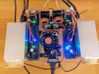
I finished my F6 amp last summer. I posted some pictures in the ”Pictures of your diy Pass amplifier thread”.
My F6 is very standard following the DIY Audio F6 build guide, all F6 key components are from DIY Store. Power supply is a standard DIY PSU with +/-18V, 300VA toroidal transformer with +-23VDC output to the amp. Bias is 600mV (1.28A). Offset is close to zero, only few mV max and stable.
After construction I made a set of measurements.
Measurement results attached:
THD vs. Power at 4.1 Ohm and 8.2 Ohm loads
THD vs. Frequency at 1W to 8.2 Ohm
I also measured output impedance which in approx. 1.2 Ohms.
I compared these results to the ones published on the Firstwatt website and found my F6 to be much worse.
Can you give any suggestions if these THD vs. Power level and THD vs frequency measurement results are normal and similar what you have measured on your F6? Can you advise if something is wrong? The difference to published specs is significant, is this OK? Should I be worried that something is wrong and my amp’s is not operating optimally?
After all the amp sounds wonderful and drives my electrostatic loudspeakers to a sufficiently high SPLs. And I’m still sleeping well!
Best regards and stay safe,
Smelay
Dear DIY fellows,
I finished my F6 amp last summer. I posted some pictures in the ”Pictures of your diy Pass amplifier thread”.
My F6 is very standard following the DIY Audio F6 build guide, all F6 key components are from DIY Store. Power supply is a standard DIY PSU with +/-18V, 300VA toroidal transformer with +-23VDC output to the amp. Bias is 600mV (1.28A). Offset is close to zero, only few mV max and stable.
After construction I made a set of measurements.
Measurement results attached:
THD vs. Power at 4.1 Ohm and 8.2 Ohm loads
THD vs. Frequency at 1W to 8.2 Ohm
I also measured output impedance which in approx. 1.2 Ohms.
I compared these results to the ones published on the Firstwatt website and found my F6 to be much worse.
Can you give any suggestions if these THD vs. Power level and THD vs frequency measurement results are normal and similar what you have measured on your F6? Can you advise if something is wrong? The difference to published specs is significant, is this OK? Should I be worried that something is wrong and my amp’s is not operating optimally?
After all the amp sounds wonderful and drives my electrostatic loudspeakers to a sufficiently high SPLs. And I’m still sleeping well!
Best regards and stay safe,
Smelay
Attachments
- Home
- Amplifiers
- Pass Labs
- F6 Amplifier