Usually I am creating from whole cloth, later finding that someone else
has already signed the guest book.
Heh well put. I used to experience this in another area of pursuit as I emerged from my teenage years ...


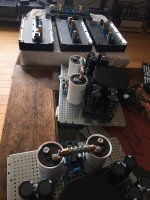
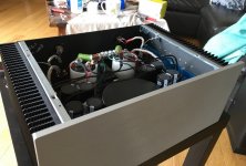
Just wrapped up 2 x F6 beasties. Excellent sounding even at break in~ 90% bias. Going to ramp them up today
Had some RIFA/Kemet PEH169 100,000uf caps that needed a home, and they got it.
Had some RIFA/Kemet PEH169 100,000uf caps that needed a home, and they got it.
Attachments
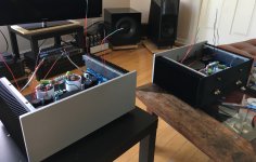
At last I have a working F6 without major issues. A few pages ago I started doing an F6 with a single rail PSU and then additionally change the feedback from voltage to current... I like my current source amplifiers but need a bit more omph on the low end than my single ended zenamp can give (but works magic for the tweeter).
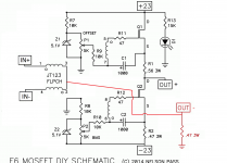
Current feedback works great, single rail supply not so much when applying feedback. I got instability problems where the amp started to oscillate massively if I fed it with a bass signal. But all was not lost as this nifty little circuit split my 48V supply into two 24V rails and now the stability issues are gone =)
The feedback schematic is like in the picture. My next step is to rewire the input side so it is as in the schematic so I get balanced inputs. Hopefully I'll get enough gain anyway and if not I'll test building a bosoz to solve that. Or use a BA-1 frontend with less gain and wire the transformer for single ended input.
I did some more cascoding tests also, the performance is good but a little bit meh as it isn't significantly better than without so just lots of complexity for very little improvement so I will probably just skip cascoding on this amp.
Attachments
Last edited:

too late as always....
no resistor in the feedback path needed to get a certain number of dB pos feedback?
Yes and no, amount of feedback is determined by the .47R to ground. Double the resistance to double the amount of feedback.
On my amp though there is no positive feedback unless I've done something wrong, just normal negative current feedback =)
In the schematic I also forgot the extra stabilising resistance in parallel of the speaker to stop capacitive loads becoming a problem. At the time I just used load resistors so It didn't pose a problem. When testing with a real speaker i put it in.
this nifty little circuit
The feedback schematic is like in the picture. My next step is to rewire the input side so it is as in the schematic so I get balanced inputs. Hopefully I'll get enough gain anyway and if not I'll test building a bosoz to solve that. Or use a BA-1 frontend with less gain and wire the transformer for single ended input.
Nice one.
I had built a balanced input version and disposed of transformers all together, but couldn't get the distortion down to where I wanted so I gave up on it.
I'm sure Papa could have done some clever trick though.
A million ideas but too dumb. That's me. Hahaha
After playing some more I'll have to revert one of my previous statements:
Cascoding works magic, it more than halves the 3rd harmonic and reduces 5th harmonic almost down to nothing.
As I have my ground at 24V potential I used a cheap isolation transformer (FGA-40HQ) for my distortion measure input and the amp input from the sound card and it turns out that this transformer was pretty bad and added lots of distortion. After running the laptop on battery and bypassing the transformer I got great distortion numbers, as good as the stock F6 without cascoding and even better with.
I have better input transformers on the way, LL1540 which I hope will let me isolate but without a big distortion penalty.
I did measure output impedance with moderate feedback (0.56R to ground) and if the calculations are correct I end up with Zout ~ 200 ohm which is high enough for me to be satisfied.
That is if the following formula is the correct way to calculate it:
(Voltage@11.77Ω - Voltage@3.77Ω) / (Current@3.77Ω - Current@11.77Ω)
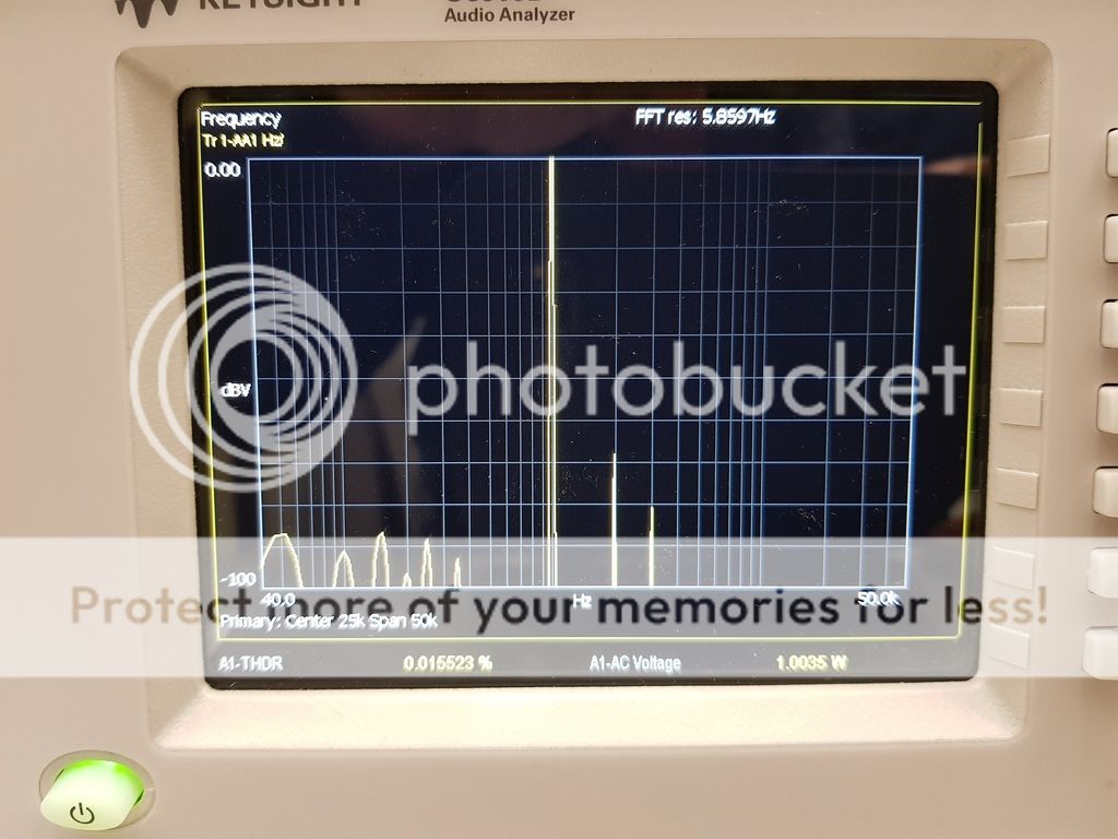
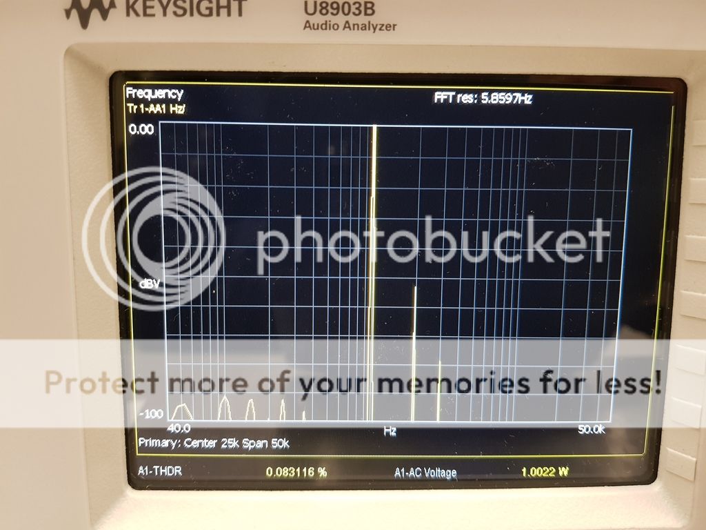
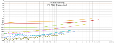
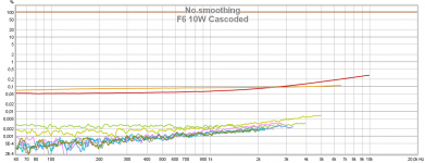
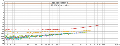
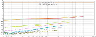
I now have data!
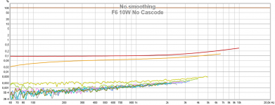
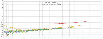
The LL1540 did solve all my problems. I now use wire them for +6 dB stepup at input which also converts the ground referenced input to my +24V virtual ground reference as my power supply is a grounded SMPS.
I set the feedback resistor at 1 ohm, and the current load is 3.8 ohm:
After looking at the data I'll have to revise my previous statement again... My current cascode setup does not improve distortion performance and so I'll do away with that.
The performance is great though so the only thing left is to combine everything into the final amplifier. I'll probably order new customized boards as they are currently a bit of a mess =)
EDIT:
Brown is fundamental.
2nd is Red
3rd is Orange
4th is Yellowish green
5th is Green
6th is Blue
7th is Pink
Attachments
Last edited:
- Home
- Amplifiers
- Pass Labs
- F6 Amplifier