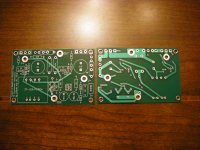
Here the Teaser-6 in stereo, installed on a heatsink and chassis previously used for an F5 built using Cviller boards.
It sounds very good. With ear 1 inch from speaker cone, no hiss and hum is barely detectable. Bass is strong and high roll-off not really noticeable. My initial impression is that something in the midrange is a bit "muddy". I need to do a lot more listening and wire up some switches so I can to A/B comparisons.
My amplifier of choice for the past year has been a balanced F5, similar to EUVL's F5X. It will be hard to beat soundwise.
nice looking , from every perspective
I would not expect same sort of quality as from balanced or even SUSY F5 ;
I would not expect same sort of quality ;
Read carefully the chosen words.
I suspect the "boomy" sound on the bass is due to a low damping factor of about 4.6. I estimate the output impedance is around 1.7 ohms. The closed-loop gain is 4.7.
F5 more versatile but must consider more than just amp with this amp.
Transformers shipped on Friday and should be there by Friday.
When faced with fine wire, a fragile pin connection and silver solder ROHS idiocy, we make the first hot pot dip in 60/40 offensive metallurgy and then over dip in 3.4% silver, 94% tin, 2.6% unknown iron pot eating materials. Not detectable.
Bud
Not too worried as i believe i will be the only limitation with this amp.
Woohoo,triple post!
Huh?  What are you really trying to say?
What are you really trying to say?F5 more versatile but must consider more than just amp with this amp.
It is impressive that the Teaser-6 sounds this good considering that with 0R47 source resistors Rs, the open-loop gain is only 20 or so. With a closed-loop gain of around 5, that doesn't leave much for feedback. One could decrease Rs, increasing open-loop gain and damping factor at the cost of changing the balance between local and global negative feedback. I haven't listened to the difference between Rs=0R47 and R2=0R12. It might be worth experimenting with.
nice looking , from every perspective
I would not expect same sort of quality as from balanced or even SUSY F5 ;
I have listened long enough to know that the Teaser-6 will NOT replace either my F5 or F5-balanced.  I am starting to have listener fatigue with this amp. Perhaps my implementation isn't up to Papa's standards, but the overall limitations imposed by the "F6 Conceptual Schematic" prevail. Bottom line: Too little open-loop gain.
Sorry to be a wet blanket.
I am starting to have listener fatigue with this amp. Perhaps my implementation isn't up to Papa's standards, but the overall limitations imposed by the "F6 Conceptual Schematic" prevail. Bottom line: Too little open-loop gain.Sorry to be a wet blanket.
Last edited:
I am eagerly waiting for them and trying to figure out what they might be. Perhaps I should tweak the circuit and its parameters some more.I expect one or few more tricks from Pa , but it's not mine to reveal them
How does this relate to the F6?
just for your amusement
pics of next (semi public) Bfish Ikebana
(we must keep this silly thread alive , or Pa will forget to publish bloody article , to stop this agony)

I expect one or few more tricks from Pa , but it's not mine to reveal them
All will be revealed on April 1st, 2013

Your loudspeakers were optimized by its manufacturer to work with an ideal voltage source amp [Zo <0.1 Ohms]. Now you drive the same loudspeakers with TEASER 6 of higher Zo = 1.7 Ohms. TEASER 6 gave you [and us] the correct and expected answers. Your build is A+. Its got power, low %THD, is stable with no hum and buzz. Unfortunately, its loudspeaker mate is suboptimal. What is Zo for your F5 build?I suspect the "boomy" sound on the bass is due to a low damping factor of about 4.6. I estimate the output impedance is around 1.7 ohms. The closed-loop gain is 4.7.
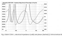
- Do know the impedance versus frequency curve of your loudspeaker especially in the midrange; to explain the mud and listener fatigue?
- The classic designs used a voltage gain stage on the primary side of the transformer. kasey197 used a step up transformer to harness more open loopl gain than available as depicted by Conceptual F6. You also have indicated other options to lower Zo!
Here is Stereophile Mag's impedance measurement of my B&W CDM1 speakers. Yup, my next tweak will be to lower the output JFET source resistors to somewhere near ZERO ohms, which will increase open-loop gain to around 100 or so. I could also reduce the closed-loop gain below 4.7, requiring an input source capable of higher voltage drive.
Your loudspeakers were optimized by its manufacturer to work with an ideal voltage source amp [Zo <0.1 Ohms]. Now you drive the same loudspeakers with TEASER 6 of higher Zo = 1.7 Ohms. TEASER 6 gave you [and us] the correct and expected answers. Your build is A+. Its got power, low %THD, is stable with no hum and buzz. Unfortunately, its loudspeaker mate is suboptimal. What is Zo for your F5 build?
- Do know the impedance versus frequency curve of your loudspeaker especially in the midrange; to explain the mud and listener fatigue?
- The classic designs used a voltage gain stage on the primary side of the transformer. kasey197 used a step up transformer to harness more open loopl gain than available as depicted by Conceptual F6. You also have indicated other options to lower Zo!
Attachments
buzzforb. I second you opinion and first point you made earlier. You also build and know loudspeakers very well.That was the point i was mqking earlier.
- Home
- Amplifiers
- Pass Labs
- F6 Amplifier