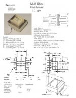
Hmmmm I appear to need to provide an updated data sheet. Much better low level 20 Hz performance than I originally showed. I apologize.
Bud
looks good enough for me

feel free to send some , for proper disposal

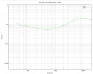
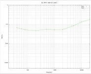
I am still stumped by Nelson Pass post #435. Both my prototype build and simulations show increased THD at both frequency extremes, but most at high frequencies. In the simulations, the interwinding capacitances are a major contributor to the high frequency 2nd order harmonic. Below are THD vs Frequency sweeps for open-loop, Gain=10 and Gain=5, and my circuit schematic.
If Nelson's results are significantly different from these, then his circuit has some tricks that I haven't figured out.
If Nelson's results are significantly different from these, then his circuit has some tricks that I haven't figured out.
I don't think you do understand. The capacitance of the transformer would
only influence the distortion at higher frequencies, not at lower, but when
we look at the open loop (or closed loop) distortion of the F6 prototype
we don't see an increase in distortion at the frequency extremes.
Remember that the quadfilar windings have symmetric capacitance, so all
windings exhibit the same conditions with respect to that.

Attachments
lhquam, i have it set up like your first chart right now, with Rs=0.47R and no feedback (battery biased for convenience). At 1khz i get THD at 0.017% (1 watt) so not far from yours. I'll check the THD at 10 and 20khz tonight and let you know what I find.
Separately, did you ever manage to measure the output impedance ? For the first case you have (open loop, Rs=0.46R) I'm getting approx 30 R.....
Separately, did you ever manage to measure the output impedance ? For the first case you have (open loop, Rs=0.46R) I'm getting approx 30 R.....
Last edited:
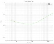
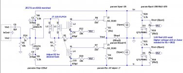
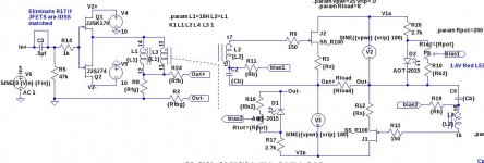
Here is a circuit that has flat open-loop THD vs Frequency like Nelson posted.
The circuit cancels most of the 2nd harmonic distortion due to the transformer interwinding capacitances. The output power supplies float together. Out+ and Out- have resistors to ground in a manner similar to that in the circlotron, except that the Out+ resistor is split to provide the feedback attenuator.
The only unfinished part of this design is a way of deriving the V2+ and V2- voltages for the input JFETs from the floating V1+ and V1- supplies.
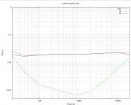
Here is the schematic and open-loop THD, H2, H3 vs Freq plot for this circuit from Spice. (H2 and H3 are the 2nd and 3rd harmonics).
This looks very good! I need to bench test it.
The circuit cancels most of the 2nd harmonic distortion due to the transformer interwinding capacitances. The output power supplies float together. Out+ and Out- have resistors to ground in a manner similar to that in the circlotron, except that the Out+ resistor is split to provide the feedback attenuator.
The only unfinished part of this design is a way of deriving the V2+ and V2- voltages for the input JFETs from the floating V1+ and V1- supplies.
Here is the schematic and open-loop THD, H2, H3 vs Freq plot for this circuit from Spice. (H2 and H3 are the 2nd and 3rd harmonics).
This looks very good! I need to bench test it.
Attachments
This seems to be a departure from the design being a circlotron. Having you tested the working version vs the sims? Perhaps the frequency roll off is a simulation issue. The specs of the Jensen do not seem to indicate a problem when it comes to either end of the frequency. You should have plenty of drive current, so that should not be an issue. Perhaps lighten up on feedback, although Melson seems to suggest his doesn't change much. Shoot for gain of 12-15dB
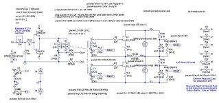
This schematic shows a circlotron resulting from a swapping of the position of lower power supply relative to the bottom FET in the schematic of post #1425 and some rearrangement in the drawing. Major difference is that the power supplies float relative to each other as well as ground and the it is difficult (or impossible) to derive the V2- voltage for the input stage.
Attachments
I am still stumped by Nelson Pass post #435. Both my prototype build and simulations show increased THD at both frequency extremes, but most at high frequencies. In the simulations, the interwinding capacitances are a major contributor to the high frequency 2nd order harmonic. Below are THD vs Frequency sweeps for open-loop, Gain=10 and Gain=5, and my circuit schematic.
If Nelson's results are significantly different from these, then his circuit has some tricks that I haven't figured out.
I sense emphasis on the work of Mr. Pass. Clearly you care and it is a challenge to refine Conceptual F6. Your published work is the proverbial bird at hand; while that of Mr. Pass is another bird perched on a distant tree! It'll come to feed off your hand in good time. It'll get hungry!
What do we know today about the work of Mr. Pass on F6? Mumm is the word.
Last edited:
Originally, Nelson used a different transformer from the Jensen. Could this explain the numbers?
........ JT123-FLPCH is still available.
This is obviously one of those days where the cosmos is playing with me.
.....

I'm understanding that as talk about originally chosen type
l. I'll check the THD at 10 and 20khz tonight and let you know ...
fwiw, in case it helps you ... at 1w, open loop, rs=0.47, 1khz=0.017%, 10khz=0.12%, 20khz=0.38% ..... Good luck ......
I'm understanding that as talk about originally chosen type
That was misunderstanding from me.
lhquam, kasey197,triode_al, and others. Would you consider laying the foundation and/or simulating the output stage of Conceptual F6 by using SIT devices instead of JFETs? You'll get an amp with an established triode-like soundprint [according to Pass, Rothacher and others]; albeit with an output impedance of hopefully <1 Ohm after using loop feedback. This Zo is much lower that is currently achieved and available. This is a Burning Amp candidate for the upcoming Festival. A Futterman-style SIT amp which will stand out in the crowd!
lhquam: Will your PCB [arriving tomorrow] accept a SIT [KD82] modification? You asked in a past post whether Mr. Pass has achieved a vac-tube sound with his F6. This approach is potentially the best answer.
lhquam: Will your PCB [arriving tomorrow] accept a SIT [KD82] modification? You asked in a past post whether Mr. Pass has achieved a vac-tube sound with his F6. This approach is potentially the best answer.
Last edited:
I do not know the circuit modifications that might be needed. Can you point me to details?
lhquam, kasey197,triode_al, and others. Would you consider laying the foundation and/or simulating the output stage of Conceptual F6 by using SIT devices instead of JFETs? You'll get an amp with an established triode-like soundprint [according to Pass, Rothacher and others]; albeit with an output impedance of hopefully <1 Ohm after using loop feedback. This Zo is much lower that is currently achieved and available. This is a Burning Amp candidate for the upcoming Festival. A Futterman-style SIT amp!
lhquam: Will your PCB [arriving tomorrow] accept a SIT [KD82] modification? You asked in a past post whether Mr. Pass has achieved a vac-tube sound with his F6. This approach is potentially the best answer.
Finally, Nelson posted the complete and detailled article about the F6!
FIRST WATT ARTICLES
Boahhh
P.S.
You see nothing new? Maybe the cache? Just press F6 !
FIRST WATT ARTICLES
Boahhh
P.S.
You see nothing new? Maybe the cache? Just press F6 !
Last edited:
I do not know the circuit modifications that might be needed. Can you point me to details?
lhquam: I have faith in your ability and others to sim and build. I am just making connections as an observer which I hope are useful. In post#921; banat showed a vacuum tube output stage in a schematic like that of Conceptual F6. A vac tube and a SIT are depletion-style devices. Guidance forward is therein. Also, the articles by Michael Rothacher entitled L'Amp: A simple SIT Amp; Parts One and Deux. They shows the characteristic curves of KD82 [measured by Rothacher], and its proper biasing. I believe that Mr. Pass has a propriatory stash [how large?] of SIT devices which are not for sale. He may be already pursuing this approach.
You're doing great with your work with JFETs. Hopefully you and others pursue SIT in addition to JFET.
Last edited:
- Home
- Amplifiers
- Pass Labs
- F6 Amplifier