more like mass hysteria ........
this is umpteenth time that Pa pulled my leg up to the sky
call me Naive ZM
- corrected schm after 290 replies
nah, Mr. Pass put my little gray cells to work; like the younger ones for many others. Was, and will be an interesting F6.
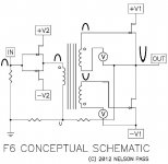
again - as drawn by Papa in post #1 , those two secondaries are in phase
and , at least by my limited knowledge of English , he confirmed that
like always - Devil is in details
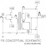
look at this - just little re-drawn , for clarity sake
blahblahblah
so now , after Papa merciful waiting to bring us proper schm ( Oh , I didn't saw that mistake ) , let's make short - this time proper - analysis :
besides biasing , simple Greedy Boy can freely expect few more tricks ......
maybe yes ........ maybe not

Attachments
Really, it was an honest mistake.......
I believe that ......... ( I'm really trying !!!!
 )
)...... The only mystery is how the circuit
worked so well that way...

well - that I can't believe
except if you made Um variation
blahblahblah
so now , after Papa merciful waiting to bring us proper schm ( Oh , I didn't saw that mistake ) , let's make short - this time proper - analysis :
besides biasing , simple Greedy Boy can freely expect few more tricks ......
maybe yes ........ maybe not
Are you mistake in this drawing intentional?
Are you mistake in this drawing intentional?
naah
not same thing again
this time I'm double double sure
Preferably by simulation. Fet cost is steep.whatever
we can now proceed to test Um variation of said circuit
David Copperfield is little kid , comparing to Papa
blahblahblah
so now , after Papa merciful waiting to bring us proper schm ( Oh , I didn't saw that mistake ) , let's make short - this time proper - analysis :
besides biasing , simple Greedy Boy can freely expect few more tricks ......
maybe yes ........ maybe not
The overall phase in non-inverting.
Attachments
The only mystery is how the circuit
worked so well that way...
I have a theory on that.

blahblahblah
so now , after Papa merciful waiting to bring us proper schm ( Oh , I didn't saw that mistake ) , let's make short - this time proper - analysis :
besides biasing , simple Greedy Boy can freely expect few more tricks ......
maybe yes ........ maybe not
Are you mistake in this drawing intentional?
The overall phase in non-inverting.
moi again ....... I flipped unflippable so many times , so my flipping brain was flipped again
to repeat proper one - just for the record
Attachments

Will this blow up?
most probably not
but biasing must be adjustable , to achieve proper 0 on output
most probably not
but biasing must be adjustable , to achieve proper 0 on output
Forgot about bias pot for upper fet.
moi again ....... I flipped unflippable so many times , so my flipping brain was flipped again
to repeat proper one - just for the record
It follows that:
- The output FETs are/must be highly matched [within the grasp of the DIYer].
- Circuit operation appears to be highly symmetric. When the upper FET is relatively on, the lower one is relatively off. When the upper FET is relatively off, the lower one is relatively on. The 2 ON states are made equal, and the 2 OFF states are made equal too. This is symmetry. Correct asymmetry with loop feedback.
- Home
- Amplifiers
- Pass Labs
- F6 Amplifier