I am working it.Good chance mine will never work. Main reason went first route, as it made sense.
Good chance mine will never work. Main reason went first route, as it made sense.
better wait 'till tonight
will re-check my idea , after daily dose of work ........ and coffee
I'm not used to think at day
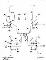
as I said - first sketch needed proofing ;
here it is , little brushing and , voila! , this will work - as I had glimpse few days ago ; just needed to recollect my gollumgollum memory what that was .....
( that day I had a thought that key is driving just one winding , and left all other details for later thinking)simmed with IRFP240 just for easiness sake
it seems I'm getting lazier each day ; using LTS for things for which I earlier used just a paper and calc
EDIT : naah ..... ooked something , as always
oomphteenth version will , eventually , work
later
Last edited:
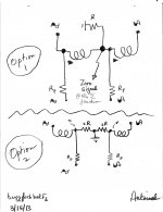
buzzforb. Please see the attachements. My initial focus is to examine the Front End [FE] of your schematic. I show two FE options. Which option meets your objective? Here is what I see in each option.I am working it.
Option 1.
- There is Zero Signal at the summing junction due to the superposition of two signals of equal amplitude and 180 degrees out phase.
- Thus, each primary winding is not "differencing" the input from its attendant output signal like in the primary winding of stand alone diy F6.
- Thus, the resultant amp may appear to operate open loop. But; I am not sure if this is a correct statement.
Attachments
flg. you are suggesting to use the power output port of the right-side amp to feedback the left-side amp. And to use the power output port of the left side amp to feedback the right-side amp. Thus the input signal to each buffer and its "bridge" feedback signal are in phase for the purpose of differencing.I thought I understood what he (ZM) said but, when I looked at the pic, I didn't get it. I think it is possible to cross couple the feedback if the phase is correct. The xfrmr wiring is the key to that phase...

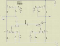
OK . here it is
two facts :
- previous one was perfect as SE input to BAL out ; sort of half SUSY .... half SUSY is same as little pregnant 
- no way that ZM's dream of driving one winding is possible ; whatever , who cares - they're all coupled anyway , so no difference
- this one will work with either SE and Bal input , like intended
I forgot what's fourth fact , but who cares .......... aha - I'm satisfied - my usual brainstorming is usually having much more brainfarts than just two ...... and is lasting longer than just few hours
two facts :
- previous one was perfect as SE input to BAL out ; sort of half SUSY .... half SUSY is same as little pregnant
- no way that ZM's dream of driving one winding is possible ; whatever , who cares - they're all coupled anyway , so no difference
- this one will work with either SE and Bal input , like intended
I forgot what's fourth fact , but who cares .......... aha - I'm satisfied - my usual brainstorming is usually having much more brainfarts than just two ...... and is lasting longer than just few hours
Attachments
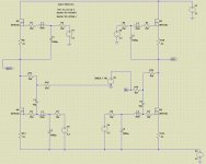
Cheapskate's versions
so - two versions for cheapskate Greedy Boyz
first one - functionally same as previous one with neg leg grounded - for CGB who is lacking in Jfets for input buffer ..... while not needing bal in
second one - for CGB , who is needing bal in , but is lacking some gnd in drawer ........ so - floating input
edit : first one was , essentially and effectively , what I posted in post #3862 , but still with messed up orientation of windings ; that's why I didn't realized that minus leg was redundant where it was .......
nasty redundantsess
gollumgollum
Attachments
Last edited:
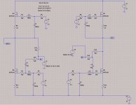
buzzforb; your schematic is repaired
The repaired schematic is attached. The basic skeleton of your schematic was untouched. The new schematic resolves the concerns of kasey197 and 6L6. The key changes are :
I was wandering how you were going to use all 4 windings. I think I am heading babelfish route. Got lots of laterals to make smoke with, figuring it out.
The repaired schematic is attached. The basic skeleton of your schematic was untouched. The new schematic resolves the concerns of kasey197 and 6L6. The key changes are :
- The input buffers were also used as signal phase inverters on the P-channel JFET side. Their load resistors are referenced to the negative rail which is also the point of connecting the source ports of the R100As. Thus, they bias and supply signals of the correct phase to the gates of the bottom R100As. So, note points A and B at the drains of the P-channel JFETs and their final gate destination.
- The secondary windings of the Jensen are connected like in diyF6. Note the phase of the signals at the gates of their attendant upper R100As. This arrangement resolves the concerns of kasey197 and 6L6.
Attachments
I am curious why you lovers of 2nd harmonic over 3rd harmonic are promoting the notion of F6X or F6-SUSY, which will kill most of the 2nd harmonic while doing nothing about 3rd harmonic. What am I missing?
That was exactly my question, but I didn't have guts to ask it, thanks
")
my guess is a net performance with a vanishing %THD.That was exactly my question, but I didn't have guts to ask it, thanks
I am curious why you lovers of 2nd harmonic over 3rd harmonic are promoting the notion of F6X or F6-SUSY, which will kill most of the 2nd harmonic while doing nothing about 3rd harmonic. What am I missing?
Sorry to stir such a controversy. I was simply looking into this for other reasons. I thought it would be interesting to see how it may sound in this configuration. I must admit i tend to prefer higher 2nd harmonic, but that is not to say i do not like the alternative. I believe there is more to the sound of an amp than just the distibution of harmonics. I liked the F6 a lot. I will probably have a SE version, no matter what. Maybe I will like this one as well. The boards of the first circuit will be here Monday and ill let you guys know what I find. I said from beginning that it may be exercise in frivolity. I just like to play around, cause sometimes you get fun little surprises.
Sorry, if I am drugging this a side, but as soon as we touch it...
I was thinking that distortion spectrum is what important here and in general in Pa's amps. Because in terms of THD there are many amps which have lower %THD(what claimed), but not sound as good as FW amps. For example look at LM based chipamp, people say they cat get several orders less THD than we are dealing with. Correct me, please.
I was thinking that distortion spectrum is what important here and in general in Pa's amps. Because in terms of THD there are many amps which have lower %THD(what claimed), but not sound as good as FW amps. For example look at LM based chipamp, people say they cat get several orders less THD than we are dealing with. Correct me, please.
my guess is a net performance with a vanishing %THD.
Certainly when I measured it for lower THD on the Distortion app, I like the sound best. I believe the transistors and iron impart there own flavors alone. Adding THD may be enjoyed by some, but not enough alone to make it sound nice.
valuable question. I hope that others give you a more satisfying answer.Sorry, if I am drugging this a side, but as soon as we touch it...
I was thinking that distortion spectrum is what important here and in general in Pa's amps. Because in terms of THD there are many amps which have lower %THD(what claimed), but not sound as good as FW amps. For example look at LM based chipamp, people say they cat get several orders less THD than we are dealing with. Correct me, please.
remember Beast ?
it is ooking pentodish complementary bridged shebang .........
and Papa said ......
it is ooking pentodish complementary bridged shebang .........
and Papa said ......
.....Recently Roger was awarded an Oscar for his lifetime of work.
......From the measurements and looking at the waveforms I had some preconceived notions
about what to expect, but I was a little surprised. Usually amplifiers with so little distortion are
a little dry and shall we say, “accurate”, and at the same time, my experience is that typically
pure third harmonic character tends to be more dynamic sounding than a second or mixed
harmonic tonality.
This amplifier is a little less dynamic than most third harmonic pieces, possibly from the lack
of feedback, but it is not dry. If it were a wine, I think of it as maybe a light auslese riesling, as
contrasted with the fat red cabernets that I like to receive from DIYers (hint, hint).
It's very slightly sweet, which is pleasantly surprising, and it has great clarity, letting a lot of
depth and detail through without any hint of aggressive qualities. Where the sweetness
comes from, I don't know.
.........Conclusion
Roger Corman turns 87 on April 5. I and many others will take a moment to appreciate his
contributions to our culture.
I just like to build amps THanks ZM. I know it gets tiresome. My schematic was just an attempt to answer single transformer question. IT kinda blew up a little. As for harmonic distribution, consider the PAss Labs stuff. If I am correct, and I am guessing here, that Nelson trys to keep the signal as clean and undistorted as possible in his amps until the very end. Like in his LEaving CLass A article, I think it is in the ouput buffer, where Nelson adds a little SE magic in the lower power range, which is phased into cancelled 2nd at higher power levels in order to handle the more complex material usually associated with these power levels. You must consider that these amps are bridged amps, so perhaps it is possible that even thogh normally a bridged, balanced fed amp would cancel even order harmonics, that perhaps they retain some of this sonic nature depsite their balanced topology. I believe he said in the BA3B thread that if each side was adjusted to higher 2nd, that even when it was run balanced, it would retain some of this character. Just a thought.
I raise the white flag
THanks ZM. I know it gets tiresome. My schematic was just an attempt to answer single transformer question. IT kinda blew up a little. As for harmonic distribution, consider the PAss Labs stuff. If I am correct, and I am guessing here, that Nelson trys to keep the signal as clean and undistorted as possible in his amps until the very end. Like in his LEaving CLass A article, I think it is in the ouput buffer, where Nelson adds a little SE magic in the lower power range, which is phased into cancelled 2nd at higher power levels in order to handle the more complex material usually associated with these power levels. You must consider that these amps are bridged amps, so perhaps it is possible that even thogh normally a bridged, balanced fed amp would cancel even order harmonics, that perhaps they retain some of this sonic nature depsite their balanced topology. I believe he said in the BA3B thread that if each side was adjusted to higher 2nd, that even when it was run balanced, it would retain some of this character. Just a thought. I raise the white flag
........ You must consider ......
Moi resume that you didn't wrote that specifically to me

from moment when Moi embraced use of these 3 & 7 legged fuses , instead of solely divine bulbs filled with Vacuum instead of smog , I simply declared indifference to fact of what some gadget is made ....... and of which concept is based - as long it sings
edit : looking at THD spectra in sim of circ(s) few posts above is - simply boring ; even looking at each halve's spectra
editedit: P.S. I'm again under Pa's disgrace
Attachments

Last edited:
Certainly when I measured it for lower THD on the Distortion app, I like the sound best. I believe the transistors and iron impart there own flavors alone. Adding THD may be enjoyed by some, but not enough alone to make it sound nice.
Says the guy who fancies the F2J
- Home
- Amplifiers
- Pass Labs
- F6 Amplifier