Single transformer.
still at first morning coffee ( it doesn't matter that noon is already ) , but it looks pretty good
something like that I had in mind , asking you to toss redundant xformer ; now just few possible iterations , focusing on feedback , to make it SUSY
like this, it isn't
disclaimer - first morning coffee ....... I'm sure later I'll see Triffids on schematic

to make it SUSY, like this, it isn't
I am working on it. Still trying to learn the general concept of both SUSY and how transformers work
disclaimer - Triffids on schematic
? Movie. Carnivorous plants.
We watched the nasties habitessses again last night. I really wish I had my horns up and running for the score of that one.
Last edited:
Zen Mod. I hope that you [unlike me] use the trade mark SUSY[R] wisely. Mr. Pass is the best judge of that. Consult the abstract of its attendant patent to feel its scope. Distance your comments from the language used in the patent by using descriptors like cancellation of distortion, mirror image, intra communication etc..still at first morning coffee ( it doesn't matter that noon is already ) , but it looks pretty good
something like that I had in mind , asking you to toss redundant xformer ; now just few possible iterations , focusing on feedback , to make it SUSY
like this, it isn't
disclaimer - first morning coffee ....... I'm sure later I'll see Triffids on schematic
Got that but imagine for a sec if you put a multimeter across the g and s for the fet, why wouldn't it read zero ? The gates are isolated at both ends and the transformer secondaries are also isolated....
Gotta work now. ill give me chance to think on it. I see what you are saying. I am trying to assemble it my head in comparison to other bridged outputs.
buzzforb. I need your blessing to suggest a possible solution to repair the schematic per the concern of kasey197.Little spin on your suggestion.
Got that but imagine for a sec if you put a multimeter across the g and s for the fet, why wouldn't it read zero ? The gates are isolated at both ends and the transformer secondaries are also isolated....
Because the voltage sources in the schematic would have to be referenced to ground and the rails, and they would be pulling the bias current. The input from the transformer would just be signal...
There is a lot of circuit in those circles with the V next to them.
buzzforb. I need your blessing to suggest a possible solution to repair the schematic per the concern of kasey197.
you dont need my blessing for anything

I was thinking along the lines of 6L6.
Because the voltage sources in the schematic would have to be referenced to ground and the rails, and they would be pulling the bias current. The input from the transformer would just be signal...
There is a lot of circuit in those circles with the V next to them.
Fair enuff - so lets get to the signal - Same issue - how do we the signal across Vgs if theyre only referenced G to G
here it is ; time for another Black Gold beverage
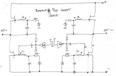
sorry - it must have 2 additional caps , if one really doesn't wanna go full Babelfish route
SUSY generated with xformer action in all 4 quadrants

note - I didn't take care about original F6 xformer phasing
sorry - it must have 2 additional caps , if one really doesn't wanna go full Babelfish route
SUSY generated with xformer action in all 4 quadrants
note - I didn't take care about original F6 xformer phasing
Attachments
Last edited:

Zen Mod. Please attach a pdf copy of your schematic to print and work with it.here it is ; time for another Black Gold beverage
sorry - it must have 2 additional caps , if one really doesn't wanna go full Babelfish route
SUSY generated with xformer action in all 4 quadrants
note - I didn't take care about original F6 xformer phasing
I was wandering how you were going to use all 4 windings. I think I am heading babelfish route. Got lots of laterals to make smoke with, figuring it out.
whatever
I can make you full DC coupled version , with integrated buffering - biasing route , but that will be too much - not so simple anymore
these feedback resistors - for their value - just multiply original F6 ones , 50-100x (say 1K8 & 10K)

better wait 'till tonight
will re-check my idea , after daily dose of work ........ and coffee
I'm not used to think at day
Zen Mod. I see a point in your schematic which may need your explanation.
- Focus on the Right side Amp
- The phase of the input signal to the non-inverting buffer is taken to be positive
- The phase of the buffer's output signal is also positive.
- The phase of the power output signal is negative.
- Consequently, the Pass negative feedback [PNF] signal to the output of the buffer has a negative phase. What is the best phase of PNF signal; positive or negative [as shown]?
- Ditto for the Left side Amp.
- Home
- Amplifiers
- Pass Labs
- F6 Amplifier