If you have luck with software that works with your Mac, please PM me.
I have been directed by MS users to try this and that, but I don't ever see anything that I am sure will work with a Mac.
Rush
Hey guys,
what are you trying to do on your macs that you are having trouble with?
If you have luck with software that works with your Mac, please PM me.
I have been directed by MS users to try this and that, but I don't ever see anything that I am sure will work with a Mac.
Rush
I have good experience with Electroacoustics Toolbox on Mac OS X
Unfortunately very expensive...

And here are other possibilities for Mac users mentioned!
Audio Measurement Apps for the Mac | InfiniteSpectra Blog
Audio Measurement Apps for the Mac | InfiniteSpectra Blog
lhquam: Please predict its OLG, Zo prior, and post feedback.Something like this?
Brgds
Hey guys,
what are you trying to do on your macs that you are having trouble with?
I may have started this by asking about a good o'scope. What I was really looking for was the ability to see second and third harmonic distortion from the F6 so as to quantify and replicate what I hear.
Thanks to all who have provided suggestions - I have a bunch of reading to do as I listen to the F6
Best
Bob
SPICE simulations show that the FQA28N15 has a transconductance of about 6.6 at 1.4A bias current. With an 8 ohm load, the open-loop gain should be about (* 2 6.6 8) = 105.6. I haven't yet made in-circuit measurements, but I would expect Zo to be similar to (maybe a little higher than) that of the F6 using the SS-R100s. SPICE predicts a closed-loop Zo of about 0.42.
lhquam: Please predict its OLG, Zo prior, and post feedback.
Brgds
Last edited:
Thanks lhquam. It is comforting your design has ample OLG to burn as expected by Mr. Pass.SPICE simulations show that the FQA28N15 has a transconductance of about 6.6 at 1.4A bias current. With an 8 ohm load, the open-loop gain should be about (* 2 6.6 8) = 105.6. I haven't yet made in-circuit measurements, but I would expect Zo to be similar to (maybe a little higher than) that of the F6 using the SS-R100s. SPICE predicts a closed-loop Zo of about 0.42.
Sheafer,
I am working on one with CRT. Enough people have been asking for one. It will use a daughter card concept to allow swapping out of transformers. It will also have enough LEDs and other options (like last schematic in F6 article) to run MOSFETs.
It will need Papa's and Variac's blessing, then I can send some out once prototyped.
I have tweaked my Teaser-6 circuit to be much closer to Nelson's F6 - Variable 2nd Harmonic schematic. The remaining differences are minor details of the bias circuits and feedback network and should not affect the sound. I removed the hack to modulate the "spare" primary winding and not have both primary windings in parallel.
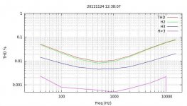
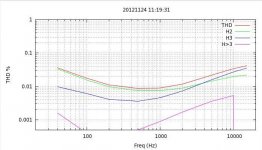
I have adjusted the THD vs Frequency sweep to be similar to that shown by Nelson. The sound is now VERY GOOD, much better than before. However, the left and right channels have rather different levels of the 3rd harmonic which is probably due to differences in the SemiSouth R100s.
Nelson: Do you have any plots of F6 2nd and 3rd harmonic vs. Frequency like the ones I show below?
Attachments
Sheafer,
I am working on one with CRT. Enough people have been asking for one. It will use a daughter card concept to allow swapping out of transformers. It will also have enough LEDs and other options (like last schematic in F6 article) to run MOSFETs.
It will need Papa's and Variac's blessing, then I can send some out once prototyped.
Thats great!
And what was wrong with layouts Alex posted before? What form factor of pcb's you are thinking of?
Nelson: Do you have any plots of F6 2nd and 3rd harmonic vs. Frequency like the ones I show below?
No. I merely look at the relative spectrum at mid-band when adjusting for
harmonics.
What ratio of H2/H3 are you looking for? Anything like 2:1?
No. I merely look at the relative spectrum at mid-band when adjusting for
harmonics.
To quote the BAF F6 talk:
"The interesting thing about this is that second and third harmonic character
correlate to a lot of people's listening preferences. I recall Jean Hiraga's
comments about liking amplifiers which have a particular amplitude
relationship between second and third harmonic (and no higher harmonics,
probably), and it appears that he preferred it over purely second harmonic.
I don't think anyone has particularly improved upon that observation – if
you're going to have some distortion, then this is likely how you would
want it. I can tell you that many of my amplifiers that have done well in the
marketplace start out at low levels being dominantly second harmonic in
character, and with increasing the power you start seeing some more third
harmonic, and somewhere below clipping the distortion is dominantly third."
I obviously need to let this steep into my brain more, or what I sometimes like to call a brain anyway. but I cant really see why the buffer cant be deleted and a balanced signal fed directly to the transformer? doesnt the transformer not care? what does the following amp stage think of a negative phase? does it care?. I would have normally thought that the input 'ground' leg of the TX is just a fake negative phase; or rather it doesnt really have phase like that, it only really has difference between the positive and ground, same as it would see the difference between positive and negative. but i'm probably missing something really basic.
go easy, i've mostly been avoiding this thread because I didnt want to convince myself I needed to build another amp... well guess what, the jfets are ordered...
i'm actually pretty sure I already have a pair of the transformers from Bud, they look identical to some of his I used with good success for a dac IV/Buffer. are they the same?
Last edited:
Qusp, if it is Dac xformer, that is the one i used. The transformer can be driven directly, but buffer is included to provide low Zo to interact well with Zin of jfet. Due to leakage current, i think, a small 10K input resistor has to be used. Using the trafo as IV stage in dac ouput and feeding utput stage directly could be interesting.
- Home
- Amplifiers
- Pass Labs
- F6 Amplifier