hello F6 sleeve 13 fans.....
I am not really good in distortion measurement (dsdjoy is much better) but astonishing at 8 Ohm and 1 Watt and Jensen I have with my Frankenstein 6 build besides k2 and a bit k3 nearly no higher harmonics, I did not see this often.......
nice
when you intend to try those biggies ?
they can be better , or not ......

Zen Mod at the moment I get a heavy oscillation using the ISKRA.
I thought I was clever enough to wire it up in the right way after the Jensen and the Edcor..... unfortunately not.
could you mark me the pins according to Jensen and sleeve 13..please.
oscillation was so heavy that the whole house was rocking....
I thought I was clever enough to wire it up in the right way after the Jensen and the Edcor..... unfortunately not.
could you mark me the pins according to Jensen and sleeve 13..please.
oscillation was so heavy that the whole house was rocking....
Attachments
kasey197: I hope that DIYers consider using bjts as a viable option in the output stage of F6. Mr Pass said in his seminar that his F6 design improved the old classic [with bjts] by referencing the biasing scheme of upper JFET to ground. And, returning loop feedback to the other lead of the primary winding of the transformer. They are real enhancements which maybe worthy to implement in an old classic revisit.Yes of course you can use different Fets.. this is a really versatile platform, a real experimenters amp if you like. I had a version of this up and running with hitachi lateral fets (2sk1058). Just a few notes if you want to use different fets:
a) swap out the leds for a 5v or so zener (most of the other fets need a higher bias voltage cf the R100s)
b) unless you add temperature compensation, stick to lateral fets (tempco can probably be handled by a thermistor across the bias pots ala F5)
c) lateral fets have much lower transconductance than the R100s so fb resistor may need to be increased.
Hope this is helpful....
Last edited:
I did a simulation of that circuit and got about the same results as with my Teaser-6 circuit. I question the choice of 470uf-1000uf for the bias coupling caps. In the simulations there is only 30 degrees phase margin at .06Hz. In the actual Teaser-6 builds with 470uf caps, the noise floor and harmonics were seen to "bounce around" significantly at a frequency of about .1-.2 Hz. When I reduced the caps to 100uf, this problem went away; verified by both the simulations and the actual builds.
I would have answered this earlier, but I just woke up.
Anyway, that's interesting, although it seems non-intuitive to me, and I
haven't run into issues over sever iterations. In any case, 100 uF is fine
with me.
Zen Mod at the moment I get a heavy oscillation using the ISKRA.
I thought I was clever enough to wire it up in the right way after the Jensen and the Edcor..... unfortunately not.
could you mark me the pins according to Jensen and sleeve 13..please.
oscillation was so heavy that the whole house was rocking....
you got positive feedback ,obviously
will search for data in PC and post
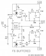
Now that the cat's out of the bag via BAF, here is the official F6 schematic.
There are several versions, but I am building 10 channels of this for in-house
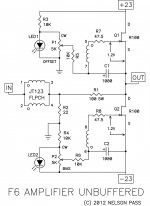
use. There is a version without the input buffer, and a couple of versions
showing degeneration on the input devices and degeneration on the outputs,
which I have not chosen to use.
There are several versions, but I am building 10 channels of this for in-house
use. There is a version without the input buffer, and a couple of versions
showing degeneration on the input devices and degeneration on the outputs,
which I have not chosen to use.
Attachments
Please clarify the underlined and/or show a schematic. Thank you.Now that the cat's out of the bag via BAF, here is the official F6 schematic.
There are several versions, but I am building 10 channels of this for in-house
use. There is a version without the input buffer, and a couple of versions
showing degeneration on the input devices and degeneration on the outputs,
which I have not chosen to use.
Zen Mod at the moment I get a heavy oscillation using the ISKRA.
I thought I was clever enough to wire it up in the right way after the Jensen and the Edcor..... unfortunately not.
could you mark me the pins according to Jensen and sleeve 13..please.
oscillation was so heavy that the whole house was rocking....
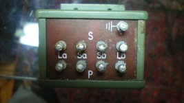
Generg , I don't have data in this pc for those repeaters
anyway - make like this :
P means primary , S means secondary
on P side , solder together ( brucke ) La pin with Sb pin ; same - Sa with Lb ;
now your primary is La-Sa , and say that La is having punkt ( use marker for that)
one secondary is La-Sa , another one is Sb-Lb
now connect sig gene (1-2Vac is enough) to primary , observe sig with scope first on primary , then on each secondary , trying to orient scope probe ( hot and gnd of it ) to have same phase as on primary
when you have that , just mark hot pin of secondary with marker
if you don't have scope near you , there is another way of doing it
edit - when you finish this , write back for exact pinout , if needed
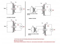
little info , for different purposes , but useful
I drew that few months ago for some greenhorns
Attachments
Last edited:
..... I am building 10 channels of this for in-house
use. ........
is that good in Papaland ?

Please clarify the underlined and/or show a schematic. Thank you.
wait for article , even if it's easy to grasp it , just listening to audio capture of Papa's BAF lecture
Cool. Do we have to be careful of input fets Idss?
Lecture - 8mA
if more , degenerate them , to keep dissipation sane
Please clarify the underlined and/or show a schematic. Thank you.
Attachments
For those who have not suffered the audio file, the question will arise about
the degeneration.
a) Like with regular feedback, I use it only when it furthers my purpose
b) Undegenerated outputs on this circuit extend the class A region at the
specified bias by about 75% more.
the degeneration.
a) Like with regular feedback, I use it only when it furthers my purpose
b) Undegenerated outputs on this circuit extend the class A region at the
specified bias by about 75% more.
Lecture - 8mA
if more , degenerate them , to keep dissipation sane
Mentioned more for others who might be tuning in for first time.
Mentioned more for others who might be tuning in for first time.
dunno
I'm the one of these two
Attachments

baaad Pa ....... 
? ?
? ?
..... I am building 10 channels of this for in-house
use. ........
is that good in Papaland ?
dunno
I'm the one of these two
Mind if I join ya, although more of a natural gift
- Home
- Amplifiers
- Pass Labs
- F6 Amplifier