Something Ive been wondering, why is it we need large >3300uF caps on output for full bass extension but only 10uf on the input?
try changing their places and see what you'll get

ACA troubleshooting
I finally got a little time to do some troubleshooting. Here are the results:
Not the back switch - I both confirmed it was working and completely de-soldered it - symptom still appears
Not the XLR - De-soldered it too - same as above.
Checked that there is nothing touching the heatsinks. There are no wires anywhere near, and PCBs are supported by nylon post, and the there are no wires anywhere near, and transistors are squarely sitting on the keratherm insulation.
Here is a weird question: Does anyone else observe this behavior? When only one input is connected to an RCA either left or right, not both, then volume is reduced and the signal (music) weakly appears out of the other unconnected channel's speaker. Perhaps this is inherent in the design?
Thanks Everyone
Any wires touching the heat sink from the back of either PCB? This is weird, there’s no obvious error showing...
I finally got a little time to do some troubleshooting. Here are the results:
Not the back switch - I both confirmed it was working and completely de-soldered it - symptom still appears
Not the XLR - De-soldered it too - same as above.
Checked that there is nothing touching the heatsinks. There are no wires anywhere near, and PCBs are supported by nylon post, and the there are no wires anywhere near, and transistors are squarely sitting on the keratherm insulation.
Here is a weird question: Does anyone else observe this behavior? When only one input is connected to an RCA either left or right, not both, then volume is reduced and the signal (music) weakly appears out of the other unconnected channel's speaker. Perhaps this is inherent in the design?
Thanks Everyone
You should absolutely not get crosstalk between channels. I would suggest disconnecting the xlr and switches. Try just connecting the rca. Make sure that the signal is getting applied to the central pin and that ground is going where it should.
Did you bias it correctly?
Did you bias it correctly?
I still think that you should do basic tests just with a multimeter, nothing turned on, and all external cables (RCAs and Speakers) disconnected and see where the problem resides:
- Do you measure continuity from input L hot-middle-pin to input R hot-middle-pin?
- Do you measure continuity between the two used pins of the back switch in position A?
- Do you measure continuity between the two used pins of the back switch in position B?
- Do you measure continuity between the XLR pins that are connected?
- Do you measure continuity between the PCB input + of channel L and PCB input + of channel R
- Do you measure continuity between one speaker output to the other (on the 'black ones', the red ones should measure continuity)
Don't just desolder things, do some troubleshooting first. It could save you a lot of time.
Hope this helps,
Rafa.
Could be wrong but - from here:
Appears that the RCA jack outer conductor is against the case and not isolated.
Follow this link - then look at your amp.

Appears that the RCA jack outer conductor is against the case and not isolated.
Follow this link - then look at your amp.
Pics for help
Last edited by a moderator:
My answers didnt suggest anything related but after thinking about it I can see output cap and load form a high passSurely you must have some kind of a guess? An intuition of some kind? When you ask yourself "in what way(s) is the input different from the output?" do any of your answers suggest anything related?
_
The thing (smartphone? CD player?) which drives the input of ACA, is not a big heavy device with large power supply and large output transistors bolted to heatsinks. It's small and modest, often battery powered.
The thing which is driven by the output of ACA (loudspeaker) is a big heavy device with large diameter wires that operate at high current. How high? Greater than 1 ampere when playing loud.
The thing which is driven by the output of ACA (loudspeaker) is a big heavy device with large diameter wires that operate at high current. How high? Greater than 1 ampere when playing loud.
laserscrape - here's the last hint before somebody actually explains it... ")
The amplifier has to operate with certain DC voltages and biases in order to get the output device to turn on, and operate. Also remember that with a single rail supply, the voltage is only as low as zero, and as high as the rail. (Bipolar supplies have positive and negative voltages)
DC operating points get the circuit to work. Also, the DC bias of the output device has to be somewhere about halfway in-between ground and the rail... because the amplifier has to make the speaker cone vibrate; that is, the amplifier's output device has to push the cone out as well as pull the cone back in order to get the vibrations.
Which means our signal, the music, is AC.
Having DC on the output will actually make the speaker cone just push out in one way and kinda stay pushed out and make a new neutral point, and the signal will make it oscillate around that new neutral. That's not ideal at all mechanically, and unnecessary heats the voice coils.
SO..... The amp has to operate with certain DC parameters for operation, but the signal (output) is only AC. Something has to keep the 150w 24v DC PSU from appearing on the speaker terminals.
laserscrape - here's the last hint before somebody actually explains it...
The amplifier has to operate with certain DC voltages and biases in order to get the output device to turn on, and operate. Also remember that with a single rail supply, the voltage is only as low as zero, and as high as the rail. (Bipolar supplies have positive and negative voltages)
DC operating points get the circuit to work. Also, the DC bias of the output device has to be somewhere about halfway in-between ground and the rail... because the amplifier has to make the speaker cone vibrate; that is, the amplifier's output device has to push the cone out as well as pull the cone back in order to get the vibrations.
Which means our signal, the music, is AC.
Having DC on the output will actually make the speaker cone just push out in one way and kinda stay pushed out and make a new neutral point, and the signal will make it oscillate around that new neutral. That's not ideal at all mechanically, and unnecessary heats the voice coils.
SO..... The amp has to operate with certain DC parameters for operation, but the signal (output) is only AC. Something has to keep the 150w 24v DC PSU from appearing on the speaker terminals.
Exquisitely concise illustration! I’ve never seen it better said anywhere.
You should absolutely not get crosstalk between channels. I would suggest disconnecting the xlr and switches. Try just connecting the rca. Make sure that the signal is getting applied to the central pin and that ground is going where it should.
Did you bias it correctly?
Well, I traced the problem and found it. I hope this helps others....
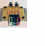
Using my M2X amp I was NOT experiencing crosstalk, when using the ACA, I was. Therefore, logically the problem was somewhere within the ACA amp. This was not quite the case. Since built, the ACA has been working without flaw as my reference work-desk amp, which is a sub-satellite configuration. I purchased a second, very nice SVS sub to compliment another room's Snell KII speakers. Here is the problem: the SVS sub has no speaker inputs/outputs, only RCA, and on the recommendation of the SVS customer service manager purchased: Russound ADP-1.2 Speaker-level to Line-level Adapter at Crutchfield.com (See attached picture)! I removed the Russound and sub and everything on both amps works fine. Testing the Russound with a DMM to see if it was badly produced showed me the answer. When wiring the banana plugs to all speker wires, I followed my strict rule that red is right and always to positive, left is black and always to negative. This worked well for the M2X, but the ACA uses a reversed system. The reds are connected to each other in the ACA and the russound has the negatives connected as together. As long as I reverse the wire pairs to the Russound when using the ACA, all works well. Reversing the speaker cables on the russound fixes the problem for the ACA and then creates the same problem on the M2X.
Attachments
Finished my second ACA amp. It went much faster this time (5-6H vs 10+) but I made a few more mistakes along the way. Nothing major but let's say I had to re-solder a few things... also the LEDs are not fitting as well for some reason. Besides remounting them I might replace them with something more subtle? Not sure yet but I don't think I can take the bright blue staring at me but I also don't want them off completely.
All-in-all a super fun project and I really appreciate how well the kit is put together including the fabulous instructions. Thank you for those responsible
As to the sound. I have a pair of OkaraOW1 / Dennis Murphy ( MurphyBlaster Productions ) Hiquphon OW1 / Vifa P13. I tore out the passive crossover and redesigned it with a miniDSP DDRC-24 a year ago. Before the ACA I was using an old Panasonic class D 6 channel amp and I was pretty happy all told. However now with the ACA it is really very clear that my crossover design is pretty terrible! So by that measure, I'd say they are very good!
The new combo is certainly sufficiently loud which was something I was wondering about. I am not sure if my line level is maxed out but with my source at an indicated 100% it is a bit louder than I like it and really it's sounding as good at 100% as it is 60%.

(I am going to reposition the amps on the lower shelf so they don't bake my speakers but this was convenient for a quick setup)
All-in-all a super fun project and I really appreciate how well the kit is put together including the fabulous instructions. Thank you for those responsible
As to the sound. I have a pair of OkaraOW1 / Dennis Murphy ( MurphyBlaster Productions ) Hiquphon OW1 / Vifa P13. I tore out the passive crossover and redesigned it with a miniDSP DDRC-24 a year ago. Before the ACA I was using an old Panasonic class D 6 channel amp and I was pretty happy all told. However now with the ACA it is really very clear that my crossover design is pretty terrible! So by that measure, I'd say they are very good!
The new combo is certainly sufficiently loud which was something I was wondering about. I am not sure if my line level is maxed out but with my source at an indicated 100% it is a bit louder than I like it and really it's sounding as good at 100% as it is 60%.
(I am going to reposition the amps on the lower shelf so they don't bake my speakers but this was convenient for a quick setup)
Last edited:
I finished my second ACA amp so I could use both in bridged configuration, mostly to get a bit more voltage gain in the system, but my LS50s do seem to be straining less with the extra power. Winning!
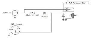
I didn't like the idea of having to switch both amps on and off all the time, so I worked out a way to do remote power switching using a cable between the XLR jacks. Just tried it and it works good, so I thought I'd throw the design out here:

The front panel power switch now feeds power to the coil of a 24v relay, which switches power to the amp. The switched 24v is also shared out the XLR with some noise filtering, some short-circuit protection, and back-to-back diodes to give about .5V drop on the cable to make sure one amp's supply doesn't try to run both amps if there's an imbalance in the voltage between the two supplies. Interconnect cable is pin-for-pin male to male.
There's no master, the configuration is symmetrical -- if either amp is turned on, the other one will turn on as well. Or you could use a small relay supply at your control center to switch on both.
I didn't like the idea of having to switch both amps on and off all the time, so I worked out a way to do remote power switching using a cable between the XLR jacks. Just tried it and it works good, so I thought I'd throw the design out here:
The front panel power switch now feeds power to the coil of a 24v relay, which switches power to the amp. The switched 24v is also shared out the XLR with some noise filtering, some short-circuit protection, and back-to-back diodes to give about .5V drop on the cable to make sure one amp's supply doesn't try to run both amps if there's an imbalance in the voltage between the two supplies. Interconnect cable is pin-for-pin male to male.
There's no master, the configuration is symmetrical -- if either amp is turned on, the other one will turn on as well. Or you could use a small relay supply at your control center to switch on both.
... also the LEDs are not fitting as well for some reason. Besides remounting them I might replace them with something more subtle? Not sure yet but I don't think I can take the bright blue staring at me but I also don't want them off completely.
I agree, they do glare. I stuffed some melted Polymorph into the holes in the front panel to make a diffuser. Optically it worked out really well, though it was a pain trying to trim the Polymorph flush with the panel without scratching the panel.
I finished my second ACA amp so I could use both in bridged configuration, mostly to get a bit more voltage gain in the system, but my LS50s do seem to be straining less with the extra power. Winning!
I didn't like the idea of having to switch both amps on and off all the time, so I worked out a way to do remote power switching using a cable between the XLR jacks. Just tried it and it works good, so I thought I'd throw the design out here:
The front panel power switch now feeds power to the coil of a 24v relay, which switches power to the amp. The switched 24v is also shared out the XLR with some noise filtering, some short-circuit protection, and back-to-back diodes to give about .5V drop on the cable to make sure one amp's supply doesn't try to run both amps if there's an imbalance in the voltage between the two supplies. Interconnect cable is pin-for-pin male to male.
There's no master, the configuration is symmetrical -- if either amp is turned on, the other one will turn on as well. Or you could use a small relay supply at your control center to switch on both.
Neat, but do you need the extra parts?
A couple of 1N4004s would do the job? You only need them in case you toggle both power switches on at the same time. Like this.
Alan
Attachments
Neat, but do you need the extra parts?
A couple of 1N4004s would do the job? You only need them in case you toggle both power switches on at the same time.
Alan
I think you're right, though I'd still retain the PTC in case of a short, and something to keep noise picked up by the long cable from entering the chassis. At least a capacitor to ground, I just happen to have those T-filters in my parts box.
My first, and it worked for a few hours !
Hi all newbie here. My first DIY amp. Enjoyed the process.
I finished it and after a few troubleshooting (cold joints etc). I managed to get it working, enjoyed the music for a few hours... and suddenly left channel no sound at all. I swear to God it worked before.
I thoroughly checked the wiring, done the test according to the troubleshooting diagram in 1.6 guide. All resistance and voltage checked out ok. Heat sinks on both sides hot.
Checked also using multi meter AC voltage and compared the good (right) and bad (left) channel. Input signal coming in but zip in the bad output channel. Test tone in the good channel showed constant voltage... nothing on the bad side.
Took the board out, checked short. Inspect all the joints. Seems good.
I have a hunch it's something obvious and stupid.... need some help, veterans here what's next to check?
Thanks a lot, Tom.
Chuttt,
It worked (?) and is hot, are good signs.
Have you checked for a short or open circuit on the input and outputs?
If you measure the resistance from the RCA outer ring to the centre you should get about 50k ohms.
If you measure from the black to red speaker connector you should get about 1k ohms.
(Or compare to your good side.)
Then as ZM says... help us see your build.
Chuttt,
It worked (?) and is hot, are good signs.
Have you checked for a short or open circuit on the input and outputs?
If you measure the resistance from the RCA outer ring to the centre you should get about 50k ohms.
If you measure from the black to red speaker connector you should get about 1k ohms.
(Or compare to your good side.)
Then as ZM says... help us see your build.
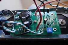
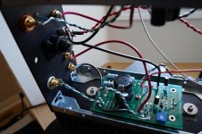
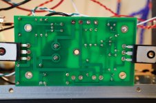
Thanks. Both RCA and speakers connection checked out ok also. Yeah it's getting stranger.... I added a few pics hope it helps. Please forgive me for the soldering. Complete novice here I know it's crappy. Looking to learn.
Attachments
- Home
- Amplifiers
- Pass Labs
- Amp Camp Amp - ACA