hey everybody, been wondering if anyone else has found errors between the layout (PCB) and the schematic. I've been noticing in the original (V1) schematic and layout that it has the + of C1 (the big output cap) connected directly to the far terminal of one P1. But according to the schematic C1 doesn't connect to the the pot. ... i have yet to find a version of this schematic that actually perfectly matched its corresponding PCB layout.
Interesting find after all this time!
You are correct, there is a difference as per xlinuxers schematic.
But as the pot is used to set 3 or 4 volts on the Gate of Q4 (and hence the 10 or 12 volts on the Drain of Q1) doesn't really matter if the pot is fed from the junction of C1, R1,2,3 and 4 or from the junction of R3,4 and Q1 drain.
I think the change improve bias stability.... But as the pot is used to set 3 or 4 volts on the Gate of Q4 (and hence the 10 or 12 volts on the Drain of Q1) doesn't really matter if the pot is fed from the junction of C1, R1,2,3 and 4 or from the junction of R3,4 and Q1 drain.
If you cut that trace from C1(+) to P1 and add a jumper from R3/R4 to P1 the PCB will match the original schematic. To add R15 to the original version you can then just connect the 2.21K resistor between the top of R8 and that lower R3/R4 junction.
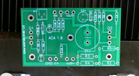
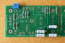
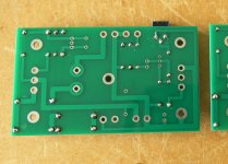
If anyone has a clear photo of both sides of either a 1.1 or 1.6 board (or the layout files) I'd be very interested to see.
If anyone has a clear photo of both sides of either a 1.1 or 1.6 board (or the layout files) I'd be very interested to see.
It's not quite right. The original schematic was correct (just without R15 added yet.) The red trace you added is connected to the wrong side of R3 (as it was mistakenly done in V1 pcb.)
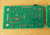
It's not quite right. The original schematic was correct (just without R15 added yet.) The red trace you added is connected to the wrong side of R3 (as it was mistakenly done in V1 pcb.)
Flavadave, I think you misread xlinuxer. Xlinuxer is pointing out what schematic layout will reflect the actual PCB construction of V1 / V1.1.
Interesting to know what effects this could have, either for better or for worse.
Also flavadave... your instructions to 'correct' the issue require to cut the trace at both sides of the PCB. Not only is the PCB weirdly built regarding the POT and C+, the trace is present at BOTH SIDES of the PCB!
")
Flavadave, I think you misread xlinuxer. Xlinuxer is pointing out what schematic layout will reflect the actual PCB construction of V1 / V1.1.
Interesting to know what effects this could have, either for better or for worse.
Also flavadave... your instructions to 'correct' the issue require to cut the trace at both sides of the PCB. Not only is the PCB weirdly built regarding the POT and C+, the trace is present at BOTH SIDES of the PCB!
yup! u r right!
Hi all,
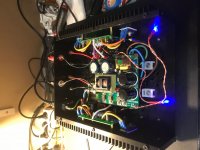
Running today for the first time my ACA.
Box open the heatsink when up to 61degre
I am afraid my build will need a fan !
Something wrong , or quite normal temperature?
Thanks
Running today for the first time my ACA.
Box open the heatsink when up to 61degre
I am afraid my build will need a fan !
Something wrong , or quite normal temperature?
Thanks
Attachments
Last edited:
Hi all,
Running today for the first time my ACA.
Box open the heatsink when up to 61degre
I am afraid my build will need a fan !
Something wrong , or quite normal temperature?
Thanks
Class A amplifiers run very hot. It's the nature of the beast. The sound more than makes up for it!

Nice build btw!!
Last edited:
Hi all,
Running today for the first time my ACA.
Box open the heatsink when up to 61degre
I am afraid my build will need a fan !
Something wrong , or quite normal temperature?
Thanks
how big is your heatsink (dimensions; K/W)?
Good catch Rafa, I didn't realize that particular trace was present on both sides.
Then you have not read all the post in this thread
It was in the very beginning we noticed this "thing". Two different ways to connect and no difference? Some components too many then?Anyway, I never used the original PCB and made my own after the circuit.
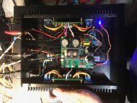
I know only the dimensions :
26x6x2 cm
Aluminum anodized black
Because you have your power supply 'in-board', I think your heatsinks and ventilation are marginal...
First, raise the chassis 20 or 25mm off the table and put the top cover on, then measure the temperatures. If they are still 60+ degrees after an hour or so do not worry. If it gets into the 70s or more, you might want to re-think it.
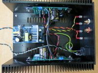
I used a slightly larger case for my build, 24 x 8 x 2.5 cm and made provision for a 80mm fan over the PSU. (Four empty holes either side of the PSU). The heatsinks on mine run 55 - 60 degrees OK, but the PSU runs at 71 degrees at its hottest spot. I never installed the fan. (Not yet anyway!)
Alan
Attachments
Question: I see in the advertisment for this amp in the store that it makes more power because of a better power supply. Would running it off a couple 12v batteries help even further? One of my amps is a Virtue M901 tripath and it made a pretty big difference to run it off batteries instead of the power supply it came with which is similar to the Meanwell on the ACA.
- Home
- Amplifiers
- Pass Labs
- Amp Camp Amp - ACA