https://www.heatsinkusa.com/10-080-wide-extruded-aluminum-heatsink/
I have a 4" tall piece of this heatsink and am curious whether I should undertake an ACA project. I doubt I could do a monoblock on the single sink eh?
I have a 4" tall piece of this heatsink and am curious whether I should undertake an ACA project. I doubt I could do a monoblock on the single sink eh?
I greet everyone. Have anyone experience with such a Kit?
Ghxamp Newest 1969M FET Pre bile Amplifier Board 1969 IRF250 Tube amplifier Board Bile Dual Channel UHC mos DC15 60V 1Pairs-in Amplifier from Consumer Electronics on Aliexpress.com | Alibaba Group
Optimal power supply of the operational amplifier and possible improvements?
Ghxamp Newest 1969M FET Pre bile Amplifier Board 1969 IRF250 Tube amplifier Board Bile Dual Channel UHC mos DC15 60V 1Pairs-in Amplifier from Consumer Electronics on Aliexpress.com | Alibaba Group
Optimal power supply of the operational amplifier and possible improvements?
Attachments
Last edited:
Thank you very much.
You have not met the PCB amplifier. Need a PCB for this amplifier.
Attachments
LongRoad, what prevents you from making a PCB yourself? Many others diyAudio members have done so, starting from ZERO prior knowledge or experience.
Here is one example: (LINK). A member from Pretoria, South Africa writes:
If he can do it, you can do it!
Here is one example: (LINK). A member from Pretoria, South Africa writes:
Around April last year, when I decided to build the ACA, no boards were available from the store. With minimal experience in electronics, I downloaded KiCad and working from the schematic and BOM, a single sided layout was produced - in case I had to etch it myself. But when I saw how inexpensive it was, I mailed the Gerbers to a board house. US$19.38 including shipping from Hong Kong, bought me 10 ACA boards (and bragging rights). The ACA amps worked first time, so no problems with my boards.
Ain't DIY fun?
If he can do it, you can do it!
The ZeroZone and other Chinese clone kits typically fail to include R15, the 2.21 kΩ resistor from base to emitter of Q3. This was an important part of the later version of the ACA which allowed it to achieve closer to 8W. It's Ok to use a BC550 instead of the ZTX450, but the 2SK246, or K30 is a dodgy replacement for the 2SK170. In all likelihood it will not perform or sound like a proper ACA, given the parts in the kit.
good to hear, ill pick one up then. it will be interesting to see how close the kit is to the photos (the same photo that 50 other sellers use) because the price does seem too good to be true.
I have some spare BF862 that might be a better choice than 2SK246 ... it will be fun trying to connect them somehow
this is a cool trick
I have some spare BF862 that might be a better choice than 2SK246 ... it will be fun trying to connect them somehow
this is a cool trick
Last edited:
Hmmm...
What I was trying to say was the Chinese "ACA Clone" kits such as this one have some problems that you will need to fix. You will want to add R15 and run the boards with a 24 Volt power supply to get the best power from them. It would also be much better to find a pair of 2SK170 or 2LS170 JFets to use for the front end. The BF862 has Ok performance, but is only available in SMD package, as you have found.
What I was trying to say was the Chinese "ACA Clone" kits such as this one have some problems that you will need to fix. You will want to add R15 and run the boards with a 24 Volt power supply to get the best power from them. It would also be much better to find a pair of 2SK170 or 2LS170 JFets to use for the front end. The BF862 has Ok performance, but is only available in SMD package, as you have found.
Ok.
The addition of R15 will increase the quiescent current through Q1 and Q2. This gives a performance boost for both 19V and 24V power. Remember that the source of Q4 (maybe BF862) runs at the gate voltage necessary to turn on Q1, or about 3.5 Volts. So Q4 does not have the full power supply voltage across it.
The Chinese kit parts are cheap, but they may or may not be original or good. You get what you pay for. You might be better off buying the bare boards, which are also available, and get the rest of the components from reliable suppliers. But then you might as well buy the bare boards from the diyAudio store and get the genuine article.
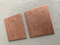
Here’s my ACA pcb - made using an engraving bit on my rotary tool but I guess you could do it with a knife. Single layer, Two jumpers. Haven’t populated them yet
No chemicals required
No chemicals required
LongRoad, what prevents you from making a PCB yourself? Many others diyAudio members have done so, starting from ZERO prior knowledge or experience.
Here is one example: (LINK). A member from Pretoria, South Africa writes:
If he can do it, you can do it!
Attachments
ah ok, lucky you mentioned this before a transformer was bought,Ok.
The addition of R15 will increase the quiescent current through Q1 and Q2. This gives a performance boost for both 19V and 24V power. Remember that the source of Q4 (maybe BF862) runs at the gate voltage necessary to turn on Q1, or about 3.5 Volts. So Q4 does not have the full power supply voltage across it.
The Chinese kit parts are cheap, but they may or may not be original or good. You get what you pay for. You might be better off buying the bare boards, which are also available, and get the rest of the components from reliable suppliers. But then you might as well buy the bare boards from the diyAudio store and get the genuine article.
still not sure about using a lm338 supply or CRC supply for it.
you can buy certain things from china ebay sellers that are really good value, examples were presoldered DIP OPA1622 and TPS7A regulators, this will be a real test.
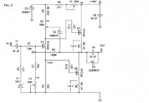
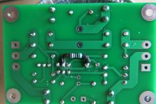
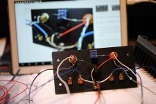
Whats visible is a different layout with awkward placement power transistor, BC550 replaced with ztx450 and 2sk170 reaplced with k246 mosfet and a diode added.
I guess they replaced rare transistors with common ones with the intention of producing cheaper kits without fakes... edit:that mosfet isnt common at all
all other components are the same so the original transistor might drop in.
as for capacitors the nichicons look authentic in the pic at least.[/QUOTE]
I used a pair of those kits for my first ACA build, (The DiyStore kits were out of stock for ages.) and I had that itch...
I ditched all the parts except for the trim pots and MosFets, they tested fine and are still working.
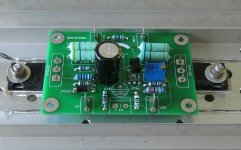
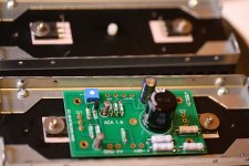
Everything else I replaced. The ZTX450s are easy to find and cheap, the 2SK170s were available in the UK at the time too. Just be aware if you do use these devices in the 'copy' kit you have to reverse them both and not follow the screen print on the boards. You can just see that on the picture.
The limitations are the size of output capacitor you can fit on the board, they are much smaller than the official ACA boards, and no space for 2.2K R15 as stated. You need to fit it to the rear which is easy enough.
They perform identically to my proper ACA 1.6 kits.
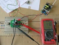
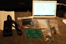
The last picture shows the £5 Chinese 24 volt SMPS I used / use.
Cheaper than all the parts to build a linear supply and again has worked flawlessly. I even tried a 10,000uF cap across it, but found it just as good without...
If you do go the linear route, don't forget each board needs 1.5 amps (class A) so build at least a 4 or 5 amp supply.
I guess they replaced rare transistors with common ones with the intention of producing cheaper kits without fakes... edit:that mosfet isnt common at all
all other components are the same so the original transistor might drop in.
as for capacitors the nichicons look authentic in the pic at least.[/QUOTE]
I used a pair of those kits for my first ACA build, (The DiyStore kits were out of stock for ages.) and I had that itch...
I ditched all the parts except for the trim pots and MosFets, they tested fine and are still working.
Everything else I replaced. The ZTX450s are easy to find and cheap, the 2SK170s were available in the UK at the time too. Just be aware if you do use these devices in the 'copy' kit you have to reverse them both and not follow the screen print on the boards. You can just see that on the picture.
The limitations are the size of output capacitor you can fit on the board, they are much smaller than the official ACA boards, and no space for 2.2K R15 as stated. You need to fit it to the rear which is easy enough.
They perform identically to my proper ACA 1.6 kits.
The last picture shows the £5 Chinese 24 volt SMPS I used / use.
Cheaper than all the parts to build a linear supply and again has worked flawlessly. I even tried a 10,000uF cap across it, but found it just as good without...
If you do go the linear route, don't forget each board needs 1.5 amps (class A) so build at least a 4 or 5 amp supply.
Attachments
Last edited by a moderator:
amazing how small it is
I see you included the diode even with original transistors, any ideas what they're for?
Im still sure how to approach the build, at first it looked like a cheap and simple amp aimed at beginners but really if power isnt a big concern then this amp is as good (if not better) than most other amps youll find. Might aswell use quality parts and a really good supply.
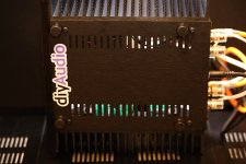
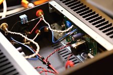
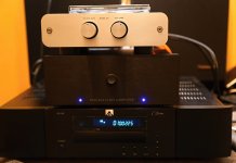
Finally did it! I figure as a degreed EE if I can't build this I may as well just hang it up and quit my job in shame. I had almost no experience soldering but I was surprised how well it all turned out. I had a little trouble soldering the barrel-type connections like the power jack and RCA connectors; I was concerned about them falling out, and it took a few tries. Tabs are much easier. I also had difficulty mounting the LEDs, the heat shrink method didn't do it for me, but Gorilla glue did. I also realize I should have used heavier gauge wire for the power to the boards.
I feel like a young kid again, listening to this incredible class-A sound from something I put together. I connected it to my TV's fixed-level audio out, and the TV audio input is fed by an AppleTV streaming music. As such I didn't have a gain control (!) and it's just a line-level signal but surprisingly I got a decent room-filling volume on my efficient 99dB Klipsch Heresy speakers.
My next step will be to pull the jumpers on my NAD integrated amp and use that as a preamp and get proper preamplification and a volume control.
Thanks SO much to Nelson Pass and everyone here for making me feel young and happy!
Link to photos with a couple of videos:
Amp build - fmalloy
Last edited:
Glad to hear of your success.
ACA's are just good fun all around.
Be forewarned; The Pass Class A sound will get to you. It wasn't long after my ACA's went into service that I was starting my 2nd build, an Aleph J and planning a 3rd, the M2x.
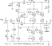
I am in no hurry, though, these ACA's in parallel mono sound good enough that I could stay here, but being one of the GreedyBoyz I wanted more.....
ACA's are just good fun all around.
Be forewarned; The Pass Class A sound will get to you. It wasn't long after my ACA's went into service that I was starting my 2nd build, an Aleph J and planning a 3rd, the M2x.
I am in no hurry, though, these ACA's in parallel mono sound good enough that I could stay here, but being one of the GreedyBoyz I wanted more.....
My friend is a guitarist in our church band. Built my first guitar amp for my step mom and he loved the sound, especially the smoothness. So I figured I will build one for him, but with an ACA.
I'll probably have a few questions in the next week or so.
If I remove, and leave open, the 2k2 resistor I will have a bias current around 1 amp, right? Heatsink is 8x3x3 so it might handle 1.5 but if not I'd like the option of dialing down.
If I replace the 5k pot with a panel mount pot and allow him to dial it how he likes in an effort to change distortion.. will there be any downside to the longevity of the amp? This might not matter a lot as I think I will build an H2 to insert distortion but I wondered if this might be an option. I can add a series resistor to keep voltage from hitting extremes.
Thanks guys and gals
Uriah
Last edited:
- Home
- Amplifiers
- Pass Labs
- Amp Camp Amp - ACA