For some projects (not ACA, not yet anyway), I have used the LED "Angel Eye" pushbutton latching switches on eBay. (here is one example among many dozens).
You do need to measure your hole and you also need to be good with LED voltage-and-current calculations to choose the correct external components so the LED glows at a sensible brightness without instantly burning out. But the cost is low and the visuals are, imho, good.
Be sure to buy one whose contacts are rated 230V (not 12V pleasure boat).
Hey.
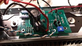
I have a troubleshooting question. Let's say a channel was working just fine. Then I decided to flip the circuit board around to match the other side. After doing so I may have rewired the amp wrong. <Facepalm>
What works right now.
Heatsink warm.
LED on.
But no turn on sound or output.
My bad wiring was:
DC input to signal input.
I don't think anything else mattered at that point. So, what do we think I fried?
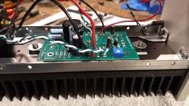
So the rest of the bad wiring was speaker output to power in and input to speaker out. I really just rotated the board 180 and resoldered without thinking.
Which cap is the input cap? C3?
Anyway to test? Remove and check with mumtimeter?
Which cap is the input cap? C3?
Anyway to test? Remove and check with mumtimeter?
Attachments
So the rest of the bad wiring was speaker output to power in and input to speaker out. I really just rotated the board 180 and resoldered without thinking.
Which cap is the input cap? C3?
Anyway to test? Remove and check with mumtimeter?
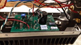
Yes C3 is the input cap, you might check it with a meter if it has a Capacitance range, but will not be conclusive unless its short or open circuit.
Have you made sure the re-soldered wires have not gone through too far and touching the chassis? And have you checked the 'bias' or done any other voltage checks from the build guide?
I will rebias. I've done the voltage checks and they are a bit off in places. I'll do them again after letting the amp warm up and post results.
I'll pull the cap and check it too.
I'll pull the cap and check it too.
Yes C3 is the input cap, you might check it with a meter if it has a Capacitance range, but will not be conclusive unless its short or open circuit.
Have you made sure the re-soldered wires have not gone through too far and touching the chassis? And have you checked the 'bias' or done any other voltage checks from the build guide?
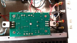
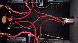
Back of circuit board.
Bias is fine at 12.05.
Will pull cap and check.
You need to re-solder all joints. Soldering is bad. At least one joint is not soldered at all.....the one just below the solder joints where the black and red wire are "soldered".
Thank you. I went back through the soldered joints everywhere. I see what you meant about the output wires. I am still hesitant to flow lots of solder through but I redid it that way.You need to re-solder all joints. Soldering is bad. At least one joint is not soldered at all.....the one just below the solder joints where the black and red wire are "soldered".
It is working properly now
Thanks for all the help.
For some projects (not ACA, not yet anyway), I have used the LED "Angel Eye" pushbutton latching switches on eBay. (here is one example among many dozens).
You do need to measure your hole and you also need to be good with LED voltage-and-current calculations to choose the correct external components so the LED glows at a sensible brightness without instantly burning out. But the cost is low and the visuals are, imho, good.
Be sure to buy one whose contacts are rated 230V (not 12V pleasure boat).
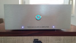
I had the same idea for my ACA which I just finished to build.
This LED switch (19mm diameter type) is easy to install and fits perfectly. It has a nice feel for switching on/off, and it provides a beautiful look to this little amp.
Two terminals are used for the incoming V+ from the external power supply and the V+ going to the pcb’s (this is similar to the stock front switch of the ACA). Then a 10k resistor can be connected between the V+ terminal (which is wired to the pcb) and the LED terminal. The 2nd LED terminal is wired to the ground bus at the back of the amplifier. The LED will turn on at the same time as the amplifier.
An affordable and simple upgrade with a nice result as you can see below
")
Attachments
Cheers for displaying that, interesting, I went down a slightly different route, although it hasn't arrived yet, and bought a vandal proof Arcoelectric push button switch, principally because I didn't want an illuminated one, and I wanted a chrome button as opposed to the black one.I had the same idea for my ACA which I just finished to build.
This LED switch (19mm diameter type) is easy to install and fits perfectly. It has a nice feel for switching on/off, and it provides a beautiful look to this little amp.
Two terminals are used for the incoming V+ from the external power supply and the V+ going to the pcb’s (this is similar to the stock front switch of the ACA). Then a 10k resistor can be connected between the V+ terminal (which is wired to the pcb) and the LED terminal. The 2nd LED terminal is wired to the ground bus at the back of the amplifier. The LED will turn on at the same time as the amplifier.
An affordable and simple upgrade with a nice result as you can see below
As the contacts are rated at 4amp inductive, I ordered a double pole switch at the same cost, so in theory I have 8A switching capacity.
Why vandal proof? It was the only chrome switch I could find with the switching capacity that wasn't a toggle switch, and I didn't have to use a relay with it.
I'm sure there are those who will now show me others..
Incidentally, I noticed in your very neat wiring there an unusual configuration on the RCA wires, it looks like a beefy ground and a much thinner signal, am I right?
We did specifically make the front power hole in the ACA compatible with 19mm vandal style switches. You will need to use a shim/spacer to center it before you tighten, but there should be 0.5mm of cover over any gaps. I spent quite a bit of time testing all kinds of 19 and 21mm switches from various manufacturers but in the end they added too many complications both electrical (most require a relay) and aesthetic. I like the capacitive ones, and you might consider an arduino compatible solid state relay. Great to see some people adding them.
Enjoying ACA’s sound
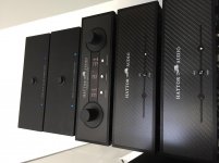
Hi there. It has been a while. This week I have time to do some listening and comparing the different worlds of amps... class D nc500 Hypex and class A ACA’s. Great way to enjoy my week of holiday.
First build a skyscraper!
Hi there. It has been a while. This week I have time to do some listening and comparing the different worlds of amps... class D nc500 Hypex and class A ACA’s. Great way to enjoy my week of holiday.
First build a skyscraper!
Attachments
Cheers for displaying that, interesting, I went down a slightly different route, although it hasn't arrived yet, and bought a vandal proof Arcoelectric push button switch, principally because I didn't want an illuminated one, and I wanted a chrome button as opposed to the black one.
As the contacts are rated at 4amp inductive, I ordered a double pole switch at the same cost, so in theory I have 8A switching capacity.
Why vandal proof? It was the only chrome switch I could find with the switching capacity that wasn't a toggle switch, and I didn't have to use a relay with it.
I'm sure there are those who will now show me others..
Incidentally, I noticed in your very neat wiring there an unusual configuration on the RCA wires, it looks like a beefy ground and a much thinner signal, am I right?
The input signal wiring was done with Amtrans single core gold plated OFC wire in PFA (similar to teflon) sleeving. I used for input ground the stock wire from the kit. The reason is because I wired the output signal with Neotech UP-OCC copper wire. You can see the difference in the red color. Neotech uses teflon insulator and highest grade copper.
jyg good move. I buy left over high quality odds and ends wire from suppliers like Redco, then split the cables and use the really good quality conductors {with superb insulation) inside. You can put these to multiple uses. My last batch had a good amount of Mogami and Canare wires, most of which is nicely shielded (the shielding can be used as ground). Some of the wire pieces I got were over 6 ft in length. Good stuff remains good stuff even if you discard the coverings, and either the whole cable or the connectors can be put to good use. The price cannot be beat.
- Home
- Amplifiers
- Pass Labs
- Amp Camp Amp - ACA