...However, I am hearing an oscillation just after power-on. It's only for a couple of seconds, it's not loud, and the amp is dead quiet once it's past. But I was just wondering if anyone else has it. It appears to be present on both channels.
Yes, a lot of us have reported this sound. Some describe it as a spring sound, you say oscillation, I called it a 'ziiiing'. We are all talking about the same behavior. Perfectly normal. It's the caps charging and the FETs stabilizing, or something like that!
")
Last edited:
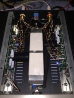
Mpitogo, really nice setup, and really nice seeing the amps share room with some heavy hitters! Thanks for sharing those pics.
I did not experience such a drastic change as days went by... my AMP behaved more or less the same always (which has always been very good). I can hear a bit of difference due to warm up, but since my heat dissipation is a lot less, it may reach that state sooner. Perhaps my other equipment is just less resolving and those changes are not as obvious. It may also be that your ears are simply better than mine!
At any rate, happy to read your story and that it has a happy ending! (Or start, because now you get to enjo.y the music!)
Best regards,
Rafa.
Last edited:
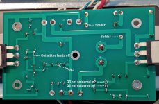
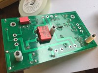
apparently no shorts to Q1 or Q2 on board #1
however r1, r2, r3 & r4 became extremely hot in short order when board powered up
Hi,
You have to re do quite a lot under there I think.
As has already been posted, you need to re-flow some solder pads, solder in Q3 and trim the leads to a much shorter length. See how that goes first!
Attachments
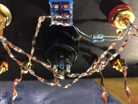
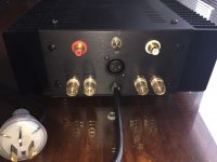
As I was building my second amp, I was mounting the rear panel connectors and couldn't remember exactly how to distribute the various insulators, lugs, washers and nuts. So I looked at my first build for reference. I noticed that on the RCA input connectors, I had the lug inserted next to the panel. That prompted me to examine the photos closely and that revealed that they should have been isolated by the insulators. I will probably unsolder them and re-do the order of the hardware, but I am wondering if it really matters if the ground of the RCA connectors are connected to the chassis.
well, for Aleph CCS , zener mod is already confirmed to soften a clipping
however , I experienced that my ears are not happy before clipping point of Aleph CCS
so , two ways from there - either build bigger Aleph , or acquire speakers better using power of existing Aleph
example - in my workshop , I'm damn happy with 3W feeding RCA LC1B in MLTL boxes , while for Tannoys in my living room (OB with Beyma 15" bass helper , so diving under 4R down) I'm happy with 10W
Cool, thanks. I will hook my test gear and play with ACA Vccs to examine its behavior, and will definitely try a zener and then drive the amp to clip to see what happens.
So, the ACA's measured correctly; they did not show any excessive ringing while I was testing them with a tone generator, 6ohm resistor and oscilloscope at around clipping point, so... I figured out what I was doing wrong that caused excessive ringing.
The ACA's have plus speaker binding posts connected to ground, I was connecting my speakers banana plugs to ACA while keeping the spades (bi-wiring) connected to my other amp... and this was, of course, shorting the ACA's negative speaker output (the actual ACA output) to ground via spades and my other amp
.Once I disconnected the spades from my other amp (removed the short), the ACA's showed what they can do.. into 4 ohms, and only 86dB efficient Dynaudio speakers. Great sound, drive, natural presentation. The bass was exceptionally defined with great texture and harmonic faithfulness to the original recording - so hard to achieve, and so underappreciated by many "audiophiles"... Everything sounded natural and relaxed... it reminded me of 2A3 and 45 single-ended tube amps, which I regard highly. There was plenty of power with ACA's. I tried 68K feedback resistor (14dB gain) but did not like the loss in cone control due to a drop in damping factor...
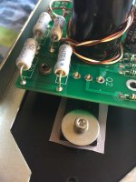
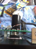
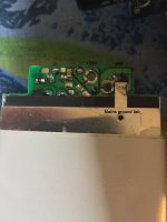
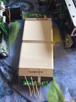
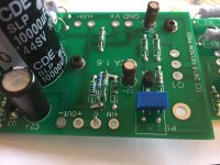
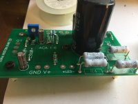
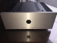
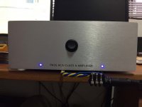
As a token of appreciation for this great kit and all the hard work that went into preparing everything required to offer it as a full kit, here are some photos of my build. The intention was to get the most out of this two gain stages, pure class A design.
WARNING - I do not recommend placing the SMPS inside the ACA to unexperienced DIY-ers. Please take this warning very seriously.
WARNING - I do not recommend placing the SMPS inside the ACA to unexperienced DIY-ers. Please take this warning very seriously.
Attachments
-
 IMG_2879.jpg158.7 KB · Views: 225
 -
 IMG_2878.jpg158.3 KB · Views: 208
 -
 IMG_2876.jpg220.8 KB · Views: 199
 -
 IMG_2875.jpg122.6 KB · Views: 182
 -
 IMG_2871.jpg112.1 KB · Views: 177
 -
 IMG_2866.jpg80.2 KB · Views: 186
 -
 IMG_2863.jpg171.2 KB · Views: 374
 -
 IMG_2859.jpg148.2 KB · Views: 375
 -
 IMG_2858.jpg112.9 KB · Views: 379
 -
 IMG_2857.jpg143.2 KB · Views: 389
I set my DMM to 00.0mv it gave me 01.7 Right 01.5 Left. The probes are touching GND and V+. Are these correct?
Thank you.
Not exactly
The idea is to measure the applied AC signal and the AC output level using a DVM to try and see why one of your channels is quieter than the other.
First disconnect the speaker. Now connect just one input socket to your player/preamp because we are testing each channel separately.
1/ Set the meter to AC voltage.
2/ Connect the black lead of the meter to the Red speaker socket (which is ground on the ACA)
3/ Connect the red lead of the meter to the Black speaker socket.
4/ Play the tone and adjust the volume to give a reasonable output voltage on the channel under test. The ACA should be able to easily reach 6 volts rms so aim for that.
(Absolute value is unimportant because we are only comparing readings and also seeing if the gain works out correctly)
Write the result down.
5/ Now transfer the red meter lead to the 'input' side of R11. This is the end that goes to the input wiring and sockets.
6/ Without altering the volume write down the reading you see.
Those two results give you an output voltage and corresponding input voltage. From those two results we can confirm if the board is working correctly.
8/ Without altering any settings now swap the input to the other channel and repeat the test. You should be seeing similar readings of output voltage and input voltage on R11.
Lets see where yours falls down on this.
I hope my DMM is up to the task (simple $20 home mart jobby), but this gives me an idea what to looking for - and how to.
Hi Cheese, there was a small error on my original (Q3 upside down DOH). Please use this one. Your meter will be fine, I used a $5 one and get similar results.
An externally hosted image should be here but it was not working when we last tested it.
I will do a similar one for voltages soon.
Alan
Attachments
As I was building my second amp, I was mounting the rear panel connectors and couldn't remember exactly how to distribute the various insulators, lugs, washers and nuts. So I looked at my first build for reference. I noticed that on the RCA input connectors, I had the lug inserted next to the panel. That prompted me to examine the photos closely and that revealed that they should have been isolated by the insulators. I will probably unsolder them and re-do the order of the hardware, but I am wondering if it really matters if the ground of the RCA connectors are connected to the chassis.
Gary,
The grounds of the RCA connectors need to be isolated from the chassis. I would address that. Not addressing it could cause ground loop issues, etc...
Best,
Anand.
mpitogo
What is the third speaker you find works well with the ACAs?
2) speaker matching, the ACA are a bit more finicky with speakers and really shine with a good efficient pair vs lesser inefficient speakers (which are adequate masked by using more powerful AB amps). I tried a couple and the third speaker was a charm.
What is the third speaker you find works well with the ACAs?
Once I disconnected the spades from my other amp (removed the short), the ACA's showed what they can do.. into 4 ohms, and only 86dB efficient Dynaudio speakers. Great sound, drive, natural presentation. The bass was exceptionally defined with great texture and harmonic faithfulness to the original recording - so hard to achieve, and so underappreciated by many "audiophiles"... Everything sounded natural and relaxed... it reminded me of 2A3 and 45 single-ended tube amps, which I regard highly. There was plenty of power with ACA's. I tried 68K feedback resistor (14dB gain) but did not like the loss in cone control due to a drop in damping factor...
Hello,
I am wondering about your last sentence. I thought the standard build spec of the ACA was 14 dB of gain. Was the 68k feedback resistor part of the original spec which you then modified for a different overall gain? If so, what resistor did you wind up using?
Thanks,
Alan
As a token of appreciation for this great kit and all the hard work that went into preparing everything required to offer it as a full kit, here are some photos of my build. The intention was to get the most out of this two gain stages, pure class A design.
Hello again,
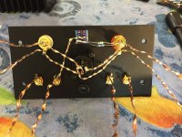
I notice you keep your resistors above the circuit board. Is there some benefit to doing so or is just so you will have extra lead if you have to re-solder them?
Thanks
Hello again,
I notice you keep your resistors above the circuit board. Is there some benefit to doing so or is just so you will have extra lead if you have to re-solder them?
Thanks
Ask Rafa why some stand off for the 3 W resistors is a good idea. A few pages back the subject of resistor heat dissipation came up.
As per ...
Any suggestions as to the minimum air gap and how to make it happen?
Maybe a spacer underneath the component during soldering that's easily removed or is it a case of bending the legs in a specific way? If the latter, feel free to offer up any tricks of the DIY trade.
Thanks ..
Hi all, found this mounting guide for power resistors. Good luck with your Build.
http://www.rcdcomponents.com/rcd/pr...ines for RCD Leaded Resistors & Inductors.pdf
Moto
- Home
- Amplifiers
- Pass Labs
- Amp Camp Amp - ACA