")
If you need a test tone (low bit rate MP3 is fine) I can post one here.
Please post it. Thanks
Last edited by a moderator:
This ebay seller has the "real stuff":
punkydawgs | eBay Stores
I have 2SK pairs under way for the BA-3 pre……and already have an 2SK170 octet for the future......BL-grade.
punkydawgs | eBay Stores
I have 2SK pairs under way for the BA-3 pre……and already have an 2SK170 octet for the future......BL-grade.
Having a think here.
<snip>
Something like this perhaps? Hope it fits in with Mr. Zen's needs too... ;-)
Alan
<snip>
Alan4411,
You're a star! Your picture is exactly what I need.
I hope my DMM is up to the task (simple $20 home mart jobby), but this gives me an idea what to looking for - and how to.
Thank you so much!
Laurens
I wasn't aware that Toshiba 2SK170BL is so scarce. I have ready access to genuine Toshiba units and would be willing to match and supply if needed. No SJ74 unfortunately.
I have built a B1 and ACA with pairs that I matched myself. So far I found pairs with Idss between 6.9mA and 10.0mA. If there is a need for quads, I can probably do that too.
.
I have built a B1 and ACA with pairs that I matched myself. So far I found pairs with Idss between 6.9mA and 10.0mA. If there is a need for quads, I can probably do that too.
.
Last edited:
Try the method I mentioned of using your meter on a low AC volts range to confirm that both channels are in fact seeing the same AC input voltage.
I set my DMM to 00.0mv it gave me 01.7 Right 01.5 Left. The probes are touching GND and V+. Are these correct?
Thank you.
I wasn't aware that Toshiba 2SK170BL is so scarce. I have ready access to genuine Toshiba units and would be willing to match and supply if needed. No SJ74 unfortunately.
I have built a B1 and ACA with pairs that I matched myself. So far I found pairs with Idss between 6.9mA and 10.0mA. If there is a need for quads, I can probably do that too.
.
Does the ACA need matched pairs? I though matched would only matter for "paralleling" devices
Does the ACA need matched pairs? I though matched would only matter for "paralleling" devices
That is my understanding. Maybe someone can confirm.
Edit: @GasCo - You are correct. No matching needed for the ACA, but hey, I sleep better knowing that they are matched. (See post #386).
.
Last edited:
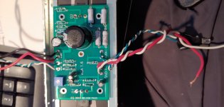
apparently no shorts to Q1 or Q2 on board #1Yes likely to be a short somewhere. Start by doing a resistance check from the Red speaker terminals (chassis ground) to the centre pins of Q1 and Q2. A zero reading (a short) will be bad.
Have a look down the back of the board and make sure there isn't a lead/wire touching the chassis etc.
Do both Q1 and Q2 warm up or just one or the other. Can you measure the bias at all before the PSU slumps?
Can you post pictures please?
Alan
however r1, r2, r3 & r4 became extremely hot in short order when board powered up
Attachments
Last edited:
If you have set the bias correctly, I think that the rising in temps for R1 ~ R4 is normal. Mine get to around 70° C (measured, as that is too hot to even touch).
Just make sure that the bias is at 12V before going ahead with the measurements, but I think that temp is expected.
Best regards,
Rafa.
Just make sure that the bias is at 12V before going ahead with the measurements, but I think that temp is expected.
Best regards,
Rafa.
apparently no shorts to Q1 or Q2 on board #1
however r1, r2, r3 & r4 became extremely hot in short order when board powered up
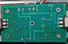
Hi CJ5,
Sorry to be blunt but you need to practice soldering a lot more.
Most solder joints on the second photo are very bad quality.
Solder has to cover smoothly the solder pad and the leg of the component.
You have potentially quite a few dry joints.
Also the legs must be trimmed short.
Have a look at all the building guides here and you'll see good examples how quality solder joint should look like.
Maybe your soldering iron is not up to the job, maybe the tip is too small, or the temperature is too low, or maybe all of the above, I don't know.
But what I know is once you eliminate these issues you'll find that a lot of the problems will go away.
Good luck.
Got mine together without instructions which is pretty much a miracle for a semi smart guy with not a lot of electronics experience. It took me 3 days of looking at pics and using common sense.
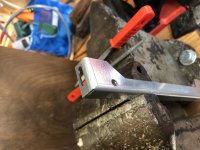
When I got it all together, the case wouldn't fit correctly. 2 weeks later I took it apart and figured out why. Make sure the hardware case rails you all received look like those in the first picture and not those in the second picture. I got a defective rail which had to be modified (by me, by enlarging the screw holes) so that parts were square. DIY Audio should be aware of this as I'm sure others had the same problem.
My only two complaints with this project are the lack of consolidated instructions in one source (at least when I built mine) and the poor quality control from the Italian Chassis manufacturer. My chassis rail was so out of whack I should have noticed it right away but YMMV.
Robie[/ATTACH]
Attachments
Hi CJ5,
Sorry to be blunt but you need to practice soldering a lot more.
Most solder joints on the second photo are very bad quality.
Solder has to cover smoothly the solder pad and the leg of the component.
You have potentially quite a few dry joints.
Also the legs must be trimmed short.
Have a look at all the building guides here and you'll see good examples how quality solder joint should look like.
Maybe your soldering iron is not up to the job, maybe the tip is too small, or the temperature is too low, or maybe all of the above, I don't know.
But what I know is once you eliminate these issues you'll find that a lot of the problems will go away.
Good luck.
ZenMod and Moly posted a spice model with voltage values across each resistor (well, resistor pair..) - so use it to confirm everything is running okay / dissipating the correct amount of heat.
Case alignment mentioned in the earlier post
The secret to case alignment was brought up in an earlier post that everybody discovered later on. Was to leave all the screws very loose so there was a lot of playing and give and then only after all screws were in place go around slowly tightening them up’ and the case will align and come together very snuggly and square . I too had a problem when putting the first case together and thought I would have to modify but then I remembered reading the post about the alignment problem and instantly loosened all the screws they fell in the place I tighten them all up and it worked exactly like it should .
Got mine together without instructions which is pretty much a miracle for a semi smart guy with not a lot of electronics experience. It took me 3 days of looking at pics and using common sense.
When I got it all together, the case wouldn't fit correctly. 2 weeks later I took it apart and figured out why. Make sure the hardware case rails you all received look like those in the first picture and not those in the second picture. I got a defective rail which had to be modified (by me, by enlarging the scrCase alignment mentioned in the earlier postew holes) so that parts were square. DIY Audio should be aware of this as I'm sure others had the same problem.
My only two complaints with this project are the lack of consolidated instructions in one source (at least when I built mine) and the poor quality control from the Italian Chassis manufacturer. My chassis rail was so out of whack I should have noticed it right away but YMMV.
Robie[/ATTACH]
The secret to case alignment was brought up in an earlier post that everybody discovered later on. Was to leave all the screws very loose so there was a lot of playing and give and then only after all screws were in place go around slowly tightening them up’ and the case will align and come together very snuggly and square . I too had a problem when putting the first case together and thought I would have to modify but then I remembered reading the post about the alignment problem and instantly loosened all the screws they fell in the place I tighten them all up and it worked exactly like it should .
experience update
Hello all,
I just wanted to post a follow up on my experience with the latest ACA kits. Originally I was not very impressed mainly for three reasons (noted below) after having had my two v1.6 monoblocks for running several weeks, I can say I’m very impressed after having had more experience with operating my units.
The build was fairly easy, 4 boards and two chassis was started on Sunday Aug 5th early morning and completely finished by later that evening with a few breaks in between for meals. The most tedious part was triple checking components and wiring, everything else was pretty straightforward. Both chassis also didn’t have assembly issues.
What I learned and maybe helpful for others.
1) break-in period, I found my amps needed a few days of playing before they really started to sing. They initially had a boxy muted, extremely warm muffled sound. After a few days on them playing various genre of music they started to sound more open and brighter.
2) speaker matching, the ACA are a bit more finicky with speakers and really shine with a good efficient pair vs lesser inefficient speakers (which are adequate masked by using more powerful AB amps). I tried a couple and the third speaker was a charm.
3) warm-up period, the ACA really need at least 30 minutes to 1 hour of warm up before they perform. IMHO I find them to open up after they’ve warmed up to operating temperature.
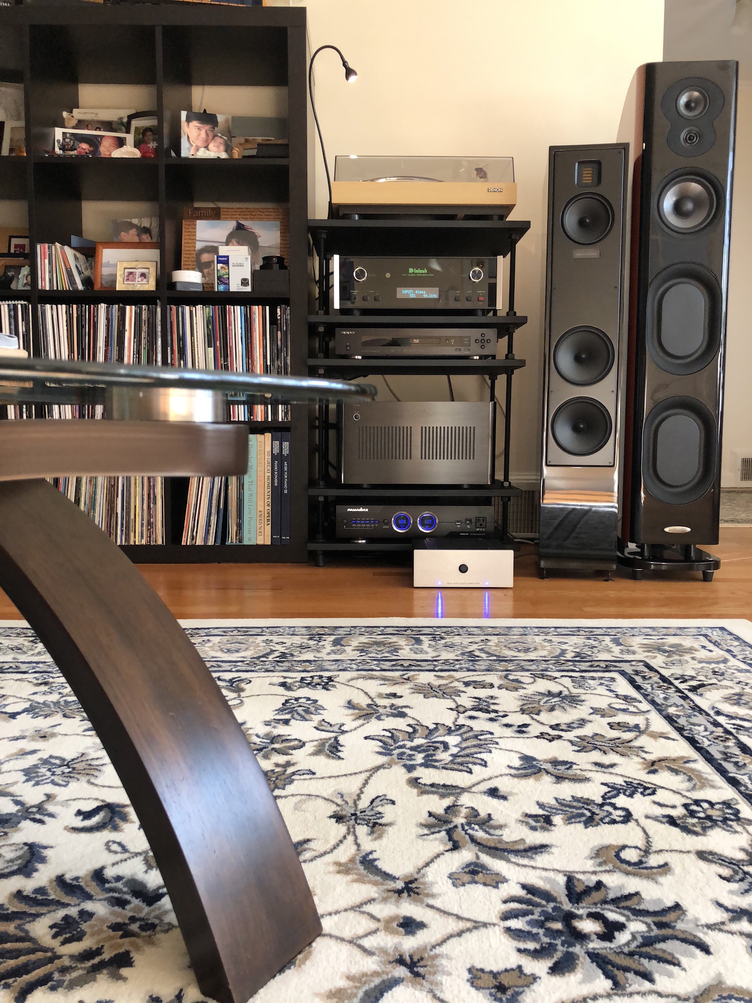
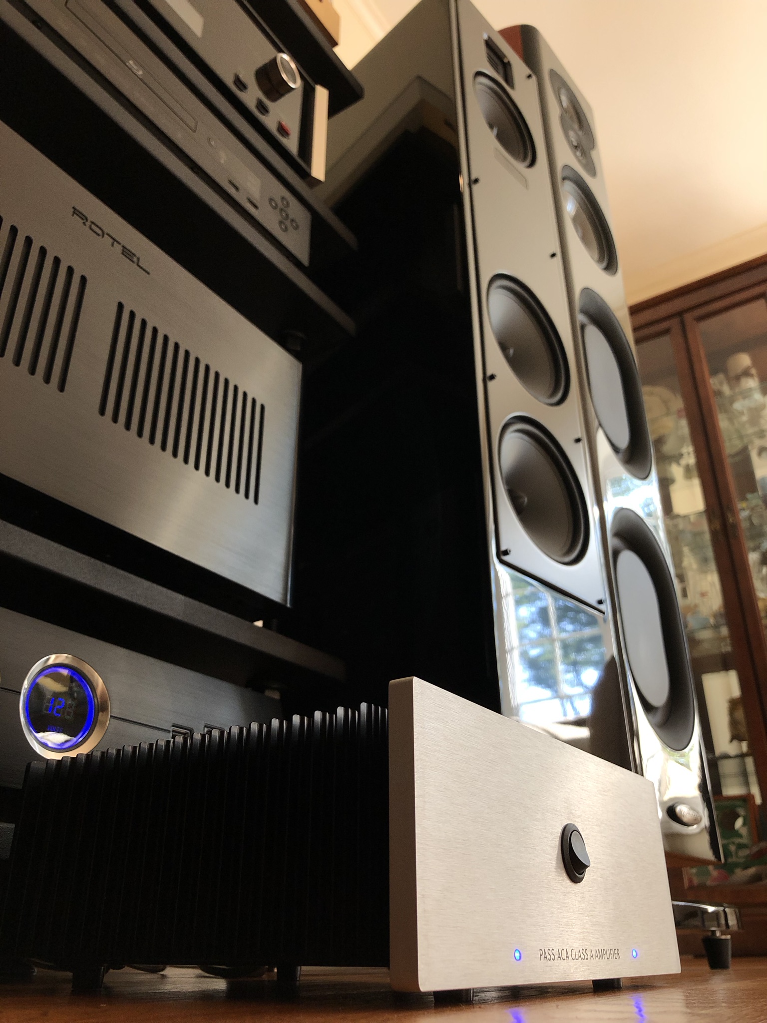
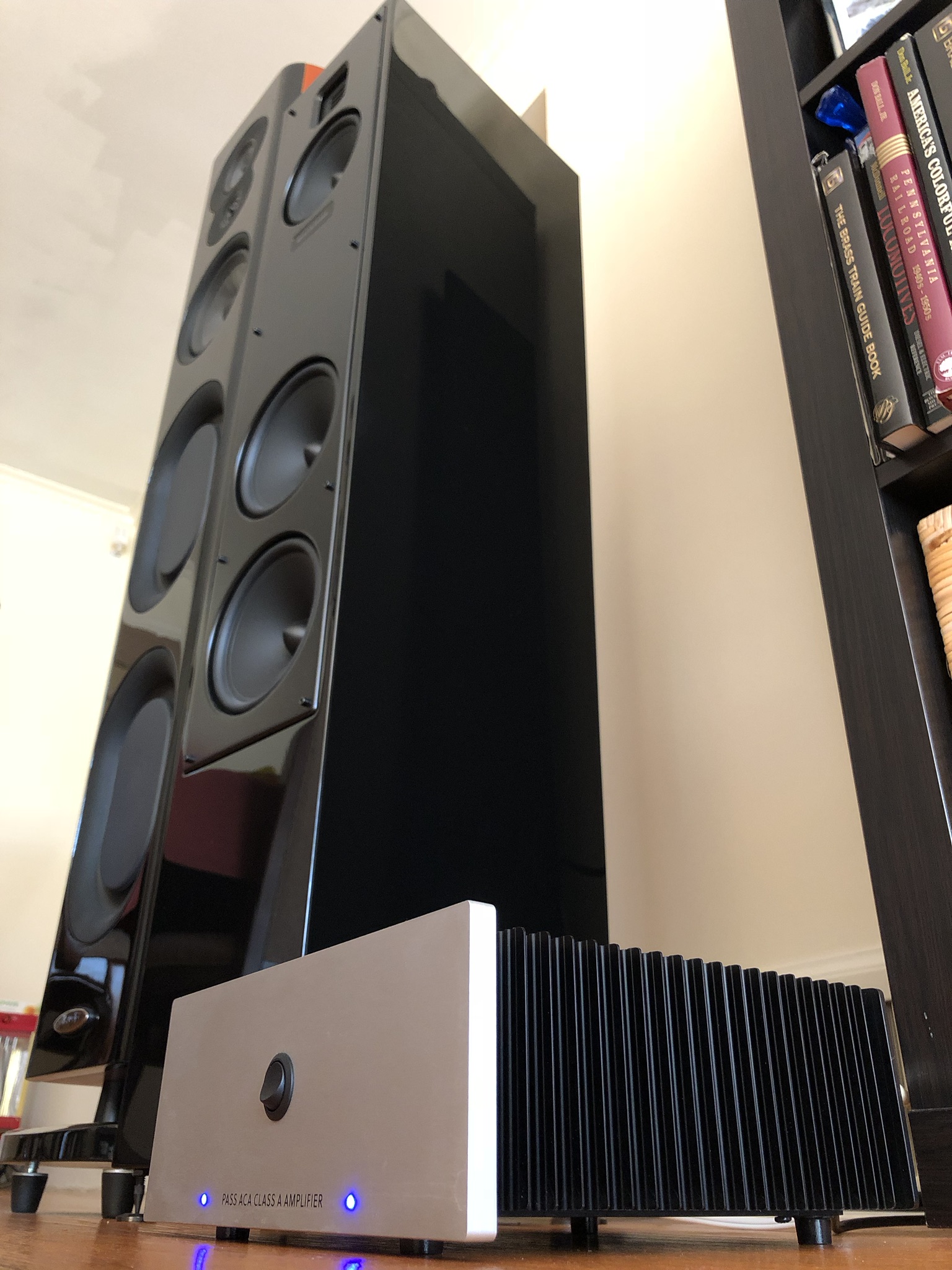
Hope you all are OK with more photos...
Kinda permanent setup, dedicated left/right monoblocks.

Hello all,
I just wanted to post a follow up on my experience with the latest ACA kits. Originally I was not very impressed mainly for three reasons (noted below) after having had my two v1.6 monoblocks for running several weeks, I can say I’m very impressed after having had more experience with operating my units.
The build was fairly easy, 4 boards and two chassis was started on Sunday Aug 5th early morning and completely finished by later that evening with a few breaks in between for meals. The most tedious part was triple checking components and wiring, everything else was pretty straightforward. Both chassis also didn’t have assembly issues.
What I learned and maybe helpful for others.
1) break-in period, I found my amps needed a few days of playing before they really started to sing. They initially had a boxy muted, extremely warm muffled sound. After a few days on them playing various genre of music they started to sound more open and brighter.
2) speaker matching, the ACA are a bit more finicky with speakers and really shine with a good efficient pair vs lesser inefficient speakers (which are adequate masked by using more powerful AB amps). I tried a couple and the third speaker was a charm.
3) warm-up period, the ACA really need at least 30 minutes to 1 hour of warm up before they perform. IMHO I find them to open up after they’ve warmed up to operating temperature.
Hope you all are OK with more photos...
Kinda permanent setup, dedicated left/right monoblocks.
Attachments

Last edited:
Hi CJ5,
Sorry to be blunt but you need to practice soldering a lot more.
Most solder joints on the second photo are very bad quality.
Solder has to cover smoothly the solder pad and the leg of the component.
You have potentially quite a few dry joints.
Also the legs must be trimmed short.
Have a look at all the building guides here and you'll see good examples how quality solder joint should look like.
Maybe your soldering iron is not up to the job, maybe the tip is too small, or the temperature is too low, or maybe all of the above, I don't know.
But what I know is once you eliminate these issues you'll find that a lot of the problems will go away.
Good luck.
No offence taken. After looking at an enlarged pic I have to agree with you completely. I guess I need new glasses or a magnifier stand. I will resolder everything and see how it goes from there.
Thanks
Up and running
Built my ACA 1.6 kit over last weekend. Not broken in yet, but it's sounding pretty good already. No problems driving a pair of KEF LS50s at normal listening levels in a small room. I'm using a M-Stage HPA-2 for a preamp.
However, I am hearing an oscillation just after power-on. It's only for a couple of seconds, it's not loud, and the amp is dead quiet once it's past. But I was just wondering if anyone else has it. It appears to be present on both channels.
- Home
- Amplifiers
- Pass Labs
- Amp Camp Amp - ACA