I agree! I thought of securing them only by two points to an L profile secured to the bottom of the chassis. It has been there, but the securing is not yet 'finalized':

Obviously, for that scenario, resting the PCB on the longer side would be a little better:

But yes, since I'm wavering the 'support' of the MOSFET legs (as used in the soldered scenario), you are right in that I need to figure out a way to add at least one more anchor point.
Thanks!
Rafa.
edit: Given that the current PCB (1.6) has a single anchor point, are two points enough? (albeit obviously in one edge therefore all the PCB has great torque capabilities over that bottom edge).
Obviously, for that scenario, resting the PCB on the longer side would be a little better:
But yes, since I'm wavering the 'support' of the MOSFET legs (as used in the soldered scenario), you are right in that I need to figure out a way to add at least one more anchor point.
Thanks!
Rafa.
edit: Given that the current PCB (1.6) has a single anchor point, are two points enough? (albeit obviously in one edge therefore all the PCB has great torque capabilities over that bottom edge).
Last edited:
Probably not an issue but heat flow will be a bit different so one component on left channel could have a lower or higher temperature than right channel and we know that electronic components change parameters with temperature. Wire layout will also be a bit different. I wont say I would be able to hear the difference. With the effort I made to make my mono blocks as identical as possible I measured the temperature on both heatsinks and there was 0.2 C between the two channels.Forgive my ignorance, but I'm having trouble understanding what the measurable / audible performance advantages would be to having the mirror imaged board layouts that MEPER has mentioned.
Well, with the current setup contenders (either vertical or horizontal PCBs) with cables to the MOSFETs as short as possible, I can put Q1 above on both channels and just cross the wires differently from one channel to the other, so this shouldn't be an issue now (I hope)
This seems like the simplest solution. It does requires to drill the heatsink (not really fan of that!):

The question is: is the Heatsinks' ability to dissipate heat lost to this setup? Ideally the MOSFETs should be in the center and next to the really think 'core' nerve of the heatsink, just as the original design. Do you think this takes much away from its ability to do its job?
Thanks again, sorry for the insecurities! Best regards,
Rafa.
This seems like the simplest solution. It does requires to drill the heatsink (not really fan of that!):
View attachment 686497
The question is: is the Heatsinks' ability to dissipate heat lost to this setup? Ideally the MOSFETs should be in the center and next to the really think 'core' nerve of the heatsink, just as the original design. Do you think this takes much away from its ability to do its job?
Thanks again, sorry for the insecurities! Best regards,
Rafa.
If you want to maximise useful air flow up the internal heat sinks, would you be able tho perforated the case's top plate? As in right above the the heat sink fins. Hot air rising and all, that might offer a better deal than the side perforations you've already got.
Maybe suck it and see?
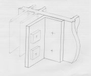
If you are thinking about mounting the FETs as in #4592 my initial reaction is don't. You achieve far better thermal distribution using the central part of the heat sink.
You could use some thick aluminium 'angle' and use the existing heat sink holes to mount it. Then you can fit the FETs and board to the other angle. Choose the best fit for the boards from there?
Sorry no design software here just old fashioned paper and pencil...
Maybe simpler to engineer than the aluminium slab muskyhunter suggests, though that would indeed give you more thermal mass to play with and let you mount the boards parallel to the sinks easier.
Attachments
Very nice drawing Alan!
The aluminum L-bracket is a nice solution and should be easy to find world wide.
I think 5mm+ thinkness should do.
I used 50x50x5mm as can be estimated in the picture, 2 amplifier modules (roughly 40W dissipation each) per Heatsink is too much in my case... 1/ amp would be perfect.
Although I think ACA will run hot on the small heatsinks, as said by someone else before, worst case just run it at 19V "only" to limit dissipation.
Last edited:
Thanks so much friends! Particularly Alan4411. Your solution really appeals to me in a lot of key aspects: simplicity, local availability, better distribution of components, avoid soldering cables to the MOSFETs, allowing the so-much-needed 3rd anchor point.
I went shopping today (took 3 days off work to do all the mechanical work for the ACA!") ) and have secured all the parts for the chassis.
) and have secured all the parts for the chassis.
I was able to find a 3.2mm thick aluminum L, just as in your drawing. 5mm was not an option.
Still, I think it may work out nicely... I had to widen a bit my design since both cards would collide with my previous target width, but its not much of a concern.
Here's my (hopefully final?) render:

From now on, lets hope what I post here are actual pictures. I'm only missing a thermal paste or compound to secure thermal integrity between the L bracket to the heatsink, and that's it.
What do you fellows think? Is it solid enough to go by that?
Thanks again so much for the input and thought into this. You may just have saved me lots of hours battling with this issues.
Best regards,
Rafa.
PS. Oh, yes I'm going to run it at 19v for the time being, for sure, thanks for the heads up.
I went shopping today (took 3 days off work to do all the mechanical work for the ACA!
) and have secured all the parts for the chassis.I was able to find a 3.2mm thick aluminum L, just as in your drawing. 5mm was not an option.
Still, I think it may work out nicely... I had to widen a bit my design since both cards would collide with my previous target width, but its not much of a concern.
Here's my (hopefully final?) render:
From now on, lets hope what I post here are actual pictures. I'm only missing a thermal paste or compound to secure thermal integrity between the L bracket to the heatsink, and that's it.
What do you fellows think? Is it solid enough to go by that?
Thanks again so much for the input and thought into this. You may just have saved me lots of hours battling with this issues.
Best regards,
Rafa.
PS. Oh, yes I'm going to run it at 19v for the time being, for sure, thanks for the heads up.
One more thought then, where does it say the two boards have to face the same way?
If you rotate the left hand assembly by 180 degrees, so the output cap is now at the bottom and facing the rear, it would be in a cooler position and the you could also arrange it so the two boards 'overlap' and still retain the narrower case profile if you wanted. (I liked it better, but that's just aesthetics...)
You are nearly there Rafa!
Running off battery
Being new to this I'm sure this question will come off silly.
Can I safely run the ACA off a 24v battery setup? I am under the impression that I would be fine as long as I use the proper sized fuse in line on the positive lead coming off the battery. If I'm correct, what size fuse should I source for the project?
Thanks,
Tom
That should be possible. You will need 30 AH battery for 10H music or so. I would use 2A fast fuse pr. amp (PCB). If you put Electrolytic capacitors after the battery the fuses should be placed after the capacitors. If not it will blow fuses during power-on. A soft charge of such capacitors is probably a good idea as current during power-on will be high from a battery (probably both battery and capacitors will get a longer life if in-rush current is reduced).
Hello,
The French used big batteries for some class A designs in the past. I have been using sealed lead batteries for a class D amplifier. Works very nice but during charging the voltage will be higher.
The newer type of batteries can be charged many times more than the old ones. THIS is important when using a class A amp. you will need to disconnect the circuit during charging.
If the caps arent that big it will work very nice. BUT in my system a LCLC sounds better than batteries and i used big batteries compared to the load presented by the circuit.
Greetings, Eduard
Indeed, both the earlier mono-block version running on 19V supply, and the new stereo chassis on 24V supply runs only warm enough that you can easily rest your hand on it. Mind you, while we've not yet run "our" recent pair bridged, I can't see how they'd run any warmer in that mode.
- Home
- Amplifiers
- Pass Labs
- Amp Camp Amp - ACA