Thanks to Mr Pass and your enthusiasm I have built the ACA and is working fine (I like its 'signature'). My only concern is that when I switch it on I hear a 'buzz' on my speakers. It only lasts for a few seconds. What could this mean? Is it a capacitor dis/charging or something more serious which could harm my speakers (not cheap)?
Thanks for any help and advice.
Thanks for any help and advice.
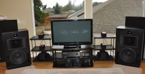
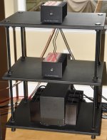
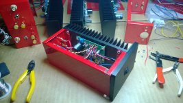
I built 4 ACA kits to drive midrange and treble compression driver/horn combos in a 3 way tri-amped stereo system using an A40 to drive the woofers. If interested in the details and not considered link spam: Advanced Acourate Digital XO Time Alignment Driver Linearization Walkthrough.
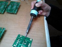
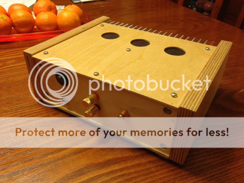
Attached are a few photos of the build and integration into the system. The white knuckles on the soldering iron belong to my 10 year old daughter who, after a quick first time tutorial on two wires, helped solder the boards. She could not believe it was liquid metal.
I have been listening for three weeks and in the last week incorporated the lets bake the amp mod. Highly recommended!
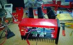
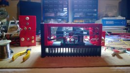
The magic combo of fast transient detail, yet liquid smooth delivery, really sets this amp apart in my opinion. For the price of the kit in the store, represents excellent value. They went together easily and I love the Ferrari red chassis!
Attached are a few photos of the build and integration into the system. The white knuckles on the soldering iron belong to my 10 year old daughter who, after a quick first time tutorial on two wires, helped solder the boards. She could not believe it was liquid metal.
I have been listening for three weeks and in the last week incorporated the lets bake the amp mod. Highly recommended!
The magic combo of fast transient detail, yet liquid smooth delivery, really sets this amp apart in my opinion. For the price of the kit in the store, represents excellent value. They went together easily and I love the Ferrari red chassis!
Attachments

Last edited:
change charger
if problem persist - you know the drill - pictures and measurements ........
Thanks will do that
")
Regards,
Sachin
say 15V is lowest value you can even think of
Hi
What would be highest value ?
Jan
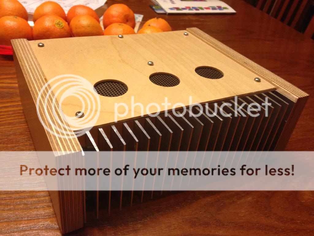
the first amp is finished!
Bravo, I like the design. Thanks for the pics.
I know Nelson has talked about 24V, but past that you need to watch the voltage ratings of the capacitors.
Hi
Thanks.
Voltage range:15-24V,correct ?
Jan
Yesterday I tried to use low DC8.5V until today also work correctly.Replace Q1 2SK1058 (g-1.4V).Hi
Thanks.
Voltage range:15-24V,correct ?
Jan
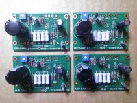
Homemade single sided ACA
My homemade version of ACA. Single sided PCB, much easier to make that double sided.
PCB specs : 4inch x 2inch, FR4 2oz.
PCB's with just the photo laminate on (before etching)

Etched PCBs

With solder mask and all holes drilled.

Getting the parts laid out.

Up and running. Didn't have the 3W resistors so used some .22Ohm/5W to make up the required values.
Sounds awesome !! Absolutely no hiss/hum.

My homemade version of ACA. Single sided PCB, much easier to make that double sided.
PCB specs : 4inch x 2inch, FR4 2oz.
PCB's with just the photo laminate on (before etching)
Etched PCBs
With solder mask and all holes drilled.
Getting the parts laid out.
Up and running. Didn't have the 3W resistors so used some .22Ohm/5W to make up the required values.
Sounds awesome !! Absolutely no hiss/hum.
- Home
- Amplifiers
- Pass Labs
- Amp Camp Amp - ACA