I have not, although I built a B1 just this morning to go with the ACA 1.8 I finished last night. The ACA has been running since I finished it to let everything settle in. I’ll do a bias check to see if it is still at 12v. I plan to take this setup to my hotel room for the AXPONA weekend.
I’ve got two as I will be doing that monoblock setup.
I have considered getting a third one to make an integrated. Korg front end, a raspberry Pi DAC and a few extra inputs.
I’ve got two as I will be doing that monoblock setup.
I have considered getting a third one to make an integrated. Korg front end, a raspberry Pi DAC and a few extra inputs.
Attachments
I actually for a long period of time I did just that. I still have tapes of resistors with their values listed on the tape next to each one in a big plastic bag that I’ve been carrying around since the eighties. Now I just go to Sonicraft and pick their L3 match for however many resistors I buy. I got my caps that way to but off hand I don’t recall where I was buying them. I just grab audionote stuff now ‘cause I’m getting lazy with caps. Tubes? Yeah… I buy those matched.
Hello everyone,
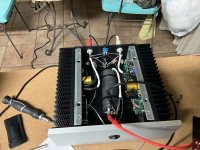
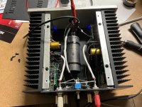
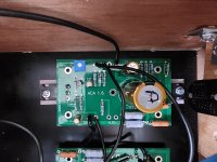
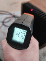
I said I'd follow up in post #11,952 regarding the ACA with TRS inputs. It was a success in terms of the TRS, but I am having a heat issue! I used 5u 250mm wave-fin heatsinks from a Dissipante chassis, each with two ACA boards (4 transistors) mounted, and expected more dissipation than the original ACA chassis. However, the amp is running FAR too hot for the given DC voltage. I have turned the trim pots all the way down to 4.44V and am still getting up to 147 deg. F (~64C) on the sinks with a 72F ambient temperature and moderate airflow after around 30 minutes. At the specified 10-12v the amplifier reaches these temps in approximately 15 minutes. (Using 24v MeanWell SMPS power supply)
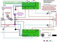
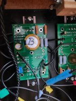
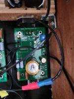
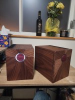
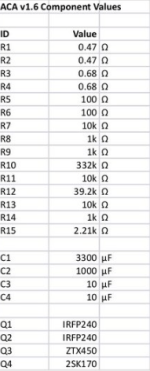
Below are photos of the boards, along with the wiring schematic and BOM we used. All resistors were double-checked before being soldered. We used all black wiring, but it was double-checked to match the schematic provided.
NOTE: The LED's are currently NOT installed on the board. Oh, and don't judge my woodworking too hard, it was done with hand tools as I'm in college!
I said I'd follow up in post #11,952 regarding the ACA with TRS inputs. It was a success in terms of the TRS, but I am having a heat issue! I used 5u 250mm wave-fin heatsinks from a Dissipante chassis, each with two ACA boards (4 transistors) mounted, and expected more dissipation than the original ACA chassis. However, the amp is running FAR too hot for the given DC voltage. I have turned the trim pots all the way down to 4.44V and am still getting up to 147 deg. F (~64C) on the sinks with a 72F ambient temperature and moderate airflow after around 30 minutes. At the specified 10-12v the amplifier reaches these temps in approximately 15 minutes. (Using 24v MeanWell SMPS power supply)
Below are photos of the boards, along with the wiring schematic and BOM we used. All resistors were double-checked before being soldered. We used all black wiring, but it was double-checked to match the schematic provided.
NOTE: The LED's are currently NOT installed on the board. Oh, and don't judge my woodworking too hard, it was done with hand tools as I'm in college!
Attachments
Hi.
First...i Like you work...nice Amp!.
Then check If your smps has the 24 V.
The heat has nothing to do with the "Operation Point" Set by the trim Pot.
Trim Pot at 4.44V each Board has 24 v with about 1.5 smps...so IT IS 36 Watt Power...Heat. you have 2 Boards...72 Watt. Too much for one Heat sink i guess
For heat ventilation use feet under your nice housing.... plus plan some ventilation holes.
What chermann said.
Use feet to raise the chassis and heat sink above the supporting surface so that air is able to enter the heat sink fins from below the heat sinks. That will help establish a vertical flow of air at the fins.
The transistors and heat sink also radiate heat into the interior of the chassis. That heat also needs to be evacuated to keep the temperature of the electronic components at a safe level for long life. It will also lower the heat sink temperature. So cooling holes/vents need to be placed in the top and bottom of the chassis. Raising the chassis also allows air to enter the chassis through vents in the bottom plate to establish air flow through the chassis to vent out at the top plate.
How long can you hold your hand on the hot heat sink? Sometimes infrared thermometers do not give accurate temperatures.
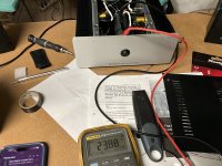
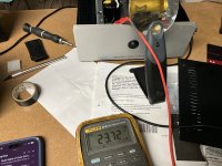
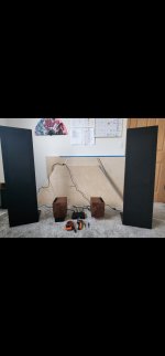
Thanks for your recommendations and compliment, I attached a photo below of them with my LRS+s and next project- a Klein Horn 😎 I improvised some feet yesterday (AMD heatsinks), and am not currently worried about internal component temperature. All the caps and resistors are well within their operating temps, the MOSFETs are hot (150F case temp) but it doesn't seem to radiate back into the chassis. (I'm guessing my rough cut edges of the magnetic sides provide some airflow.)
With the feet (3in off floor) its still in the X*?@! territory.
I'm looking a method (mod) to lower the dissipation of the amplifier. In my F5T there are resistors controlling the range of DC bias, I'm assuming its set here, so potentially increasing its resistance may help lower the dissipation. Alternatively, I could purchase 20v power supplies, has anyone compared the temperature difference?
ModuShop claims the heatsinks performs ~0.19-0.28 C/W, 57-70 above my 72 deg. room, if dissipating 72 watts (ignoring a bunch of important maths and graphs)
Attachments
Last edited:
That is some beautiful wood work.
Those heatsinks are usually installed in a metal chassis that allows more ventilation from the inside of the amp. There is also some heat transfer to the front plate and backplate. These little things add up and make a significant difference in how much thermal energy a chassis can dissipate. A standard chassis construction could easily handle the heat from two ACA boards.
If there is a way to allow some airflow from inside the chassis, that would help a lot.
The ACA has a fixed bias that is set by the 0.47 and 0.68 Ohm resistors. This is would be 1.45 Amps with those values and a 19V supply. The 24V supply increases bias to about 1.5A.
Good point about front and rear plates, they get quite hot on my F5T. I designed these amps with ply that tolerates higher temperatures without warping over time, but it doesn't dissipate heat like metal can. I'll see whats possible for ventilation tomorrow. The supply doesnt seem to make a huge (%) difference. So, if anyone knows a post with an inceased (or extra spliced in) resistor, please let me know!
Woodworking is a hobby of patience and precision to me. Tolerance goal on the Klein Horns is 1/16 in, working with 3/4 Birch ply, and mitered corners. I'll never make another project with compound (3 axis) miters, it takes an awful amount of trig.
Tags: wood amp , wood chassis
Woodworking is a hobby of patience and precision to me. Tolerance goal on the Klein Horns is 1/16 in, working with 3/4 Birch ply, and mitered corners. I'll never make another project with compound (3 axis) miters, it takes an awful amount of trig.
Tags: wood amp , wood chassis
Last edited:
Hi Dalton
normal a trim pot is on the pcb of the SMPS - so you can setup the SMPS to 19V. the trim on the ACA pcb should be adjust to the "operating point" half of that -so about 9,5-10V. measured after the big cap C1. to GND.
to set down the bias through the resistors (bias of your amp in Class A) you have to dismount the PCB and change the resistors to a higher level.
chris
I've performed my fair share of 'amplifier surgery.' Anyone have predictions of what changing the 0.47 Ohm to 0.68 ohm resistors would net me for a bias decrease, or should I be making bigger changes to the values? I'll look for a pot on the MeanWell supplies to lower output voltage 👍🏼
Ok…., so you want to affect the circuit to decrease the amps output instead of making your cooling solution work for the meager output the amp has? How about making an L shaped wooden piece that covers the sinks with an air gap at the bottom then mount two 20mm by 20mm fans in the bottom section, (it’s closed off of course) it would match your current look and you’d have more airflow past those fins as the air vents out the top. Your current vision of the circuit would thus work and you’d get to hear what it sounds like without having to fiddle with bias or further complicating the circuit with some sliding voltage/biasing power supply. KISS. A simple mechanical solution to your problem without having to do any circuit changes. Actually if it were me, I would make the base out of wood and the channel from aluminum that is painted black to match the fins. More heat sink the merrier.., oh and run bolts through the sheet to clamp it to the fins and improve the conduction of heat to the plate. Just sayin’.
Also, if memory serves. Papa picks his ‘fets to run at a bias where it sounds the best. If you are wanting a less powerful amp that runs at a lower class A current you might want to consider another MOSFET to drive with that current. Maybe find one of his builds that run at a lower power, or just ask Papa for his recommendations for what values you are trying to run your amp on. I am sure he has heard every one of those things ever made.
You can decrease the bias current by decreasing the value of R8. Try paralleling a resistor to the existing resistor. This should be easy to do as you do not need to take the board off the heat sink. Try paralleling another 1k resistor to the existing 1k. That may reduce the current perhaps 15 percent. You can reduce the value of R8 further if you want an even lower bias current. Lower bias current does affect amplifier performance though.
I strongly recommend that you provide air flow to the interior of the amplifier. Without air flow the internal temperature will be high after a long period of operation. Electrolytic capacitor lifespan is highly dependent on their temperature. An 10 degree C increase in temperature halves their lifespan, and each 10 degree C increase halves their lifespan again. It is best to keep electrolytic capacitors as cool as possible.
Since you have nice wood enclosures that you probably do not want to mess up, one way to provide some air flow through the chassis is to add some venting to the chassis bottom plate toward the front of the chassis for air entry and some venting toward the top of the back plate for air exit. That hopefully would provide some air flow through the chassis to evacuate some heat that radiate from the mosfets.
Another way to decrease the bias current is to eliminate R15. The original ACA did not include this part.
Ben has mentioned some good ideas for improving airflow, which I would recommend before reducing the bias current.
Edit:
Reducing voltage and bias current are at odds with good sound from this amp. The most recent work that has been done with the ACA includes a 30V linear PSU, 1.6A bias current and high transconductance Mosfets. The good news is only a single board is needed for each channel. There is another thread that discusses these mods.
Last edited:
I've performed my fair share of 'amplifier surgery.' Anyone have predictions of what changing the 0.47 Ohm to 0.68 ohm resistors would net me for a bias decrease, or should I be making bigger changes to the values? I'll look for a pot on the MeanWell supplies to lower output voltage 👍🏼
About 15% reduction in current.
I'm battling some RF noise on my ACA when using it on my desktop setup, and wondering if anyone could help troubleshoot.
Setup: Macbook Pro -> Sony TAZH1es Pre-out -> ACA -> Coral Holey Basket open baffle diy.
I'm getting bad RF noise when moving things on the desktop of the computer, ie moving the mouse makes noise through the system.
Swapping out the ACA For a cheap topping tripath amp completely removes the issue, so I'm fairly confident its coming from the ACA and not my non-sheilded speakers.
So far nothing i've tried has worked including:
Appreciate any suggestions, these speakers sound great with the ACA and I'd like to use them together")
Setup: Macbook Pro -> Sony TAZH1es Pre-out -> ACA -> Coral Holey Basket open baffle diy.
I'm getting bad RF noise when moving things on the desktop of the computer, ie moving the mouse makes noise through the system.
Swapping out the ACA For a cheap topping tripath amp completely removes the issue, so I'm fairly confident its coming from the ACA and not my non-sheilded speakers.
So far nothing i've tried has worked including:
- Moving ACA and Sony onto a filtered furman power strip
- physically moving the speakers
- physically moving the components +- 3' (within range of the cabling)
Appreciate any suggestions, these speakers sound great with the ACA and I'd like to use them together
I will take a stab at this..
If your ACA is properly enclosed inside its chassis, and I assume it is, then the RF noise is entering the amp through the RCA cables and being amplified. It may be worthwhile to try a different set of RCA interconnect cables, as some are better shielded than others.
Another thing to try is reducing the internal gain of the ACA to higher frequencies. I use different values for some components when I build my ACAs. I set R11 to 20k and R12 to 90.9k. I also add a 10pF capacitor (mica or polystyrene) in parallel with R12. This does increase the overall gain slightly, while reducing gain of RF.
Thanks for the recommendations @TungstenAudio!
Your post invigorated me to keep trying things. I swapped out RCA cables, moved everything away from the screen, and then googled my specific monitor (LG 5k thunderbolt 3) and found this post discussing how the monitor was interfering with nearby speakers. the solution there was to lift ground on the monitor using a cheater plug (3 prong to 2 prong adapter), and much to my surprise this worked!
I'm not too fond of this solution as I power the laptop over USB-C via this monitor, so i'm going to try to swap it out for a different screen that hopefully doesn't share this issue.
I hope thats helpful if anyone else experiences issues with noise from a LG model 27MD5K.
- Home
- Amplifiers
- Pass Labs
- Amp Camp Amp - ACA