Perfect, thank you!there are banana plugs in the ACA. try to look at the photo of the backpanel in the ACA ver.1.8 build guide
Simulation doesn't tell the whole story. Build it, disconnect the feedback and listen with a full range (no crossover) speakers connected with reverse phase. It may change your mind.Amp Camp Amp, ACA, is not to be used without Feedback
My simulations shows this.
THD without feedback 2.2%
THD with feedback 0.3%
An update on my build and a shout out to Solmer. I received my second ACA kit and sucessfuly assembled it. The kit was missing the 4 10uF capacitors and I sent a Email to DIY store and never heard back from them. Never the less I outsourced them and finished the build. and it acually works..So I revisited the first attempt with the loud hum and finally noticed I had assempled the input RCA's wrong with the ground washer against the faceplate. I fixed the problem and now I have monoblcks driving my 2way Cornscallas..
I do have a couple of follow up questions though. I am still confused with the talk of phase reversal. What does that mean for my speaker connects? Also, why are so many audiophiles concerned with speaker wires when the inside wiring from the pcb to the binding posts is what, 20 ga.?
I do have a couple of follow up questions though. I am still confused with the talk of phase reversal. What does that mean for my speaker connects? Also, why are so many audiophiles concerned with speaker wires when the inside wiring from the pcb to the binding posts is what, 20 ga.?
The ACA inverts phase. All that means is when the input signal goes in a positive direction, the output goes the other way. The speaker cone moves in the opposite directions for an inverting amp vs a non inverting.I am still confused with the talk of phase reversal. What does that mean for my speaker connects?
There is much controversy over whether it matters or is audible. To correct inverting phase all you do is swap the speakers wires around so - and + are reversed. Can you hear a difference or not?
The ACA circuit itself inverts phase, the ACA as a finished product does not and that is achieved simply by swapping the speaker connections around internally in the amp. The end user is non the wiser.
Hi udtcharlie congratulations with your amps. I had not seen the wrongly placed washers but now that you mention it, it is visible on the photos.the ground washer against the faceplate. I fixed the problem and now I have monoblcks driving my 2way Cornscallas..
")
Request for power supply insights replicating here from the ACA premium thread:
https://www.diyaudio.com/community/threads/aca-amp-with-premium-parts.328357/post-7328117
https://www.diyaudio.com/community/threads/aca-amp-with-premium-parts.328357/post-7328117
My ACAs have the original 19V power supplies. After a recent power outage I am noticing a lot more static through the speakers. I disconnected the source RCAs and it is still noticeable. Next step was to hook it up to a bench supply and determine if the power bricks are the culprit. Anything else to check?
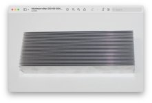
Looking at the fins, the spacing of fins is about 69mm/26 = 2.65mm. Clear space between fins is less. For reasonably effective natural convection cooling, the minimum clear space between fins needs to be about 6 or 7mm. Less than that and the air stagnates between the fins, not moving well to transfer heat away from the heat sink.
With closely spaced fins, forced air is needed.
With closely spaced fins, forced air is needed.
- Home
- Amplifiers
- Pass Labs
- Amp Camp Amp - ACA