I understand that's how it's hooked up, but how does it work? Presumably I'm not thinking of this right, but it surprises me that a speaker-level output is being fed into a line-level input. The resistor will reduce the current, I take it, but what's really going on here?
I tried googling this, but what I found e.g. on Wikipedia does not describe this kind of circuit. What they show is more like a balanced circuit.
I tried googling this, but what I found e.g. on Wikipedia does not describe this kind of circuit. What they show is more like a balanced circuit.
It’s a nifty arrangement that takes full advantage of the simple fact that the amplifier is inverting.
The signal comes in from the source, right side up, through the L channel RCA and then is amplified…and in that process inverted.
The inverted output is present on the L channel speaker black, and we will call that Speaker (-), and attach the black terminal of the speaker there.
That same signal (which remember is upside down) goes through the 39,000ohm resistor, where it’s reduced in amplitude, and as the amplifier input needs no current to speak of, is now happily the same size as the original signal from the RCA input… except it’s still inverted.
This upside down signal now goes to the input of the R channel, where it is amplified and inverted again , becoming right-side-up, and this output of the R channel is on R speaker black, we’ll call this Speaker (+) and attach the red terminal of the speaker here.
The music comes out, it sounds great, and as the output is taken from the two hot speaker posts, the total voltage swing can be doubled, and in theory the power is now quadrupled! But of course there’s no thing as a free lunch… the load seen by the amplifier channels is halved, so your 8 ohm speakers appear to the amp as 4 ohm and your 4 ohm speakers 2, etc.. resulting in the simple fact that you’ll run out of current capability before you hit the theoretical quadrupling of power. That said, the increase in power is quite real, noticeable, and in my opinion, bridged ACA sounds better than standard, into 8 and 4 ohm speakers both.
The inverted output is present on the L channel speaker black, and we will call that Speaker (-),
That's where I had to look at on the circuit board and see that the "+" is really ground and "-" is really amp out.
I understand why it was labelled that way, but I find it confusing.
Playing around with a passive preamp this week, but am getting ground noise...
Still can't kill the noise
 and have traced it directly to the Dynavector P75 Mk3 phono preamp. It is an ungrounded device that uses a wallwart for power. Notes for this device read, "...The P75 is not earthed. An earth terminal is provided on the rear panel that will allow the P75 to be connected to a ground point if required."
I see that if using the ACA in balanced mode then pin 1 goes to ground. Does it seem safe to connect the ACA pin 1's together at the passive preamp, then connect them to the Dynavector's earth terminal? Thanks.
I am a complete beginner with electronics
Just finished my aca build and went to set the dc balance voltage on P1 trimpot
Red channel adjusts ok
White channel reads approx 22 volts and adjusting the trim pot does nothing at all
It stays at 22v no matter what
Using pin2 on Q1
Any ideas ??
Just finished my aca build and went to set the dc balance voltage on P1 trimpot
Red channel adjusts ok
White channel reads approx 22 volts and adjusting the trim pot does nothing at all
It stays at 22v no matter what
Using pin2 on Q1
Any ideas ??
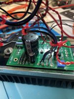
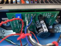
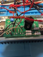
Here are photos of problem board
Thank you
Also I don’t have any inputs or speakers hooked up
Thank you
Also I don’t have any inputs or speakers hooked up
Attachments
Last edited:
It's difficult to see the components clearly on the board, especially the colour bands on the resistors. An overhead shot of the board that is closer in and sharply in-focus would be very helpful.
One resistor to check is R9. Make sure it is 1k Ohm. And measure the voltage across R9. It should be 4V or so.
One resistor to check is R9. Make sure it is 1k Ohm. And measure the voltage across R9. It should be 4V or so.
Wow —- thanks for all of the help
I am a 63 year old who for some dumb reason decided to try to learn electronics for my stereo stuff
Never underestimate my ability to make a mistake
I am more of a mechanical person
Printing press type equipment for my whole live
Always stayed away from electronics and 480 volt mains coming into my business 😂
Rikiheck wins the fixer price
My sloppy soldering skills had one of the wires on the back side of the board touching the heatsink
I fixed that and now the trim pot seems to be adjusting properly
Short lived good news
Ok after my last post I went and hooked everything up to test with speakers
I used a set of pioneer 6 ohm bookshelves and a Yamaha c4 preamp
Music played for about 2 minutes then the left ( white input ) side shut down completely and the right channel keep playing music
I immediately shut everything off and let it sit for a bit
About an hour later I turned the aca back on with no speakers or inputs attached
Still no power in the white channel
The heatsink did not warm up
The led turned on and there was 24v at the lead ins to the circuit board - I checked this with my voltmeter
I turned it off and called it a day
Next day I powered it up and the led turned on again and this time there was heat coming from the white channel heatsink
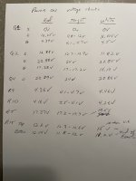
I downloaded and printed out the “test” photos for no power resistance checks and also the powered on voltage check points
The results of these measurements are in the attached photos
I am no expert but maybe R15 on white channel is a problem? It was giving me erratic voltage readings — jumping around and then finally settling down after a couple of minutes and this was after a 25 minute warmup of the amp
And if so what is the fix?
I have not hooked this back up to a preamp or speakers again
Not sure what to do
Thanks for looking
Ok after my last post I went and hooked everything up to test with speakers
I used a set of pioneer 6 ohm bookshelves and a Yamaha c4 preamp
Music played for about 2 minutes then the left ( white input ) side shut down completely and the right channel keep playing music
I immediately shut everything off and let it sit for a bit
About an hour later I turned the aca back on with no speakers or inputs attached
Still no power in the white channel
The heatsink did not warm up
The led turned on and there was 24v at the lead ins to the circuit board - I checked this with my voltmeter
I turned it off and called it a day
Next day I powered it up and the led turned on again and this time there was heat coming from the white channel heatsink
I downloaded and printed out the “test” photos for no power resistance checks and also the powered on voltage check points
The results of these measurements are in the attached photos
I am no expert but maybe R15 on white channel is a problem? It was giving me erratic voltage readings — jumping around and then finally settling down after a couple of minutes and this was after a 25 minute warmup of the amp
And if so what is the fix?
I have not hooked this back up to a preamp or speakers again
Not sure what to do
Thanks for looking
Attachments
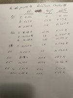
Voltage measurements are what is needed.
Firstly make sure you have 24 volts on the board itself and then check that it is reaching the middle leg of Q2 and that there is no voltage on the Source of Q1 (right hand end pin looking at it from the front).
It is most likely a bad joint somewhere or a floating zero volt line to the board.
Firstly make sure you have 24 volts on the board itself and then check that it is reaching the middle leg of Q2 and that there is no voltage on the Source of Q1 (right hand end pin looking at it from the front).
It is most likely a bad joint somewhere or a floating zero volt line to the board.
Sorry, for some reason I missed seeing all those...
The 12 volts midpoint is an important value and if that's in the right ballpark then it usually means the main DC conditions are basically correct.
R15 result needs rechecking. This is the current regulator for the output stage. Measure across the resistor for accuracy and you should see no more than around 0.7 volts (the base/emitter drop of Q3). If it's much higher than that then we have a problem.
So recheck that first and see where it leads us.
- Home
- Amplifiers
- Pass Labs
- Amp Camp Amp - ACA