The ACA definitely sounds better with higher rail voltage and a corresponding higher 'bias' voltage at the Drain of Q1. Mine now run at 28V from a CRCRC filtered linear supply (300VA, 24V toroid) and 14.5V Drain bias. I use IRFP140 Mosfets at Q1 and Q2; others have reported great results with FQH44N10 Mosfets.
That's interesting because I wired mine as dual mono with a dual linear supply with an unregulated voltage of around 25vdc. The transformers are 18vac. I read that someone was using 30vdc with no ill effects. I have tried the bias voltage at 12.5v, but will see what a bit higher does.The ACA definitely sounds better with higher rail voltage and a corresponding higher 'bias' voltage at the Drain of Q1. Mine now run at 28V from a CRCRC filtered linear supply (300VA, 24V toroid) and 14.5V Drain bias. I use IRFP140 Mosfets at Q1 and Q2; others have reported great results with FQH44N10 Mosfets.
Wow. I need to read more.there is also 48Vdc ACA
I plotted results of different set bias Voltages for the original 19V ACA version in post 576 of this thread. THD changes above 1KHz or so. When I ask if the rise in THD in the high end was a flaw or a feature, nobody answered.Can anyone tell me what effect (good or bad) increasing or decreasing the voltage measured on the drain of Q1 from 10v for 19v PS or 12v for 24volts? I am just curious.
I finished my 2nd aca amp just like the 1st (it works) and it does not work at all…I had to change out some resisitors that I was short in my kit (R11 10K 1ea short I got 10K 1/4 watt)..(R13 10K 2ea short…I got 2ea 10K 1/4 watt)…(R6 100ohm 1 ea short….I got 100 ohm 1/4 watt)…this is what diy audio told me toget…it acts like the wattage is wrong as I have quadruple checked everything….help???? is this the right resistance but the wrong wattage,,,should it have been 3 or 4 watts????
I had to change out some resisitors that I was short in my kit (R11 10K 1ea short I got 10K 1/4 watt)..(R13 10K 2ea short…I got 2ea 10K 1/4 watt)…(R6 100ohm 1 ea short….I got 100 ohm 1/4 watt)…is this the right resistance but the wrong wattage,,,should it have been 3 or 4 watts???? The left channel does not play at all no mater the dpdt switch position...Help plz...newb! aca amp2nd build (1st works//)
It is the same question you asked 12 hours ago and you have 2 replies ")
The wattage is fine.
If the amp does not work at all then first check that the supply is present and correct (24 volts on Q2 middle pin). Check that you have approx 12 volts on R1/2/3 and 4. Confirm the FET's get hot.
Maybe post some clear pictures of your build too?
The boards and wiring.
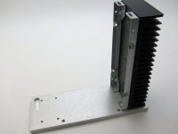
Not sure if this is the right place to post this, but I'm pretty sure the holes are drilled in the wrong place on my amp's face plate.
When comparing to photos in the guide, there are a number of significant differences


When comparing to photos in the guide, there are a number of significant differences
- The holes aren't close enough to attach each side. I've loosened the side rails and wiggled them out as far as possible, the holes don't line up
- The holes are near the edge of the face plate. So even if I could attach the sides to the faceplate, the sides would be too far apart for the top and bottom to span. See the last image
- Also, the holes aren't threaded, it looks like they are intended to use with a nut on the oher side.
edit.....
anybody willing to take a pic of same front plate, to see screw holes?
as if both pairs are missing, at inner side of FPlate
FP is of proper size, as I see it, heatsink sides need to go closer, according to bottom/top plate size
editedit - now I'm officially confused - no M4 holes/taps on back side of FPlate, and there are 4 holes in corners
no such ones in pics above this post
Last edited:
I'm confused?
When was there an ACA front plate with exposed screw holes.
Wormboy, clearly something very odd with that particular front panel... return it for a proper replacement.
From the build guide for a picture of the normal internal screw places.
When was there an ACA front plate with exposed screw holes.
Wormboy, clearly something very odd with that particular front panel... return it for a proper replacement.
From the build guide for a picture of the normal internal screw places.
Attachments
Last edited:
- Home
- Amplifiers
- Pass Labs
- Amp Camp Amp - ACA