Simple, swap left and right input leads round. If the left channel is now louder and the right channel is 'light' your problem is not the ACA, but your DAC/preamp whatever. You should also make sure the speakers are not the problem by swapping them round too.As for inputs being equal, can you give an example as I do understand?
10-4Simple, swap left and right input leads round. If the left channel is now louder and the right channel is 'light' your problem is not the ACA, but your DAC/preamp whatever. You should also make sure the speakers are not the problem by swapping them round too.
Oddly, after moving things around, switching from parallel and stereo makes no difference in audio levels between speakers. I'm now wondering if I didn't have something connected correctly.
I'm going to run it for a couple of days and see if something changes (in theory nothing should), if not, id say we have a winner.
Thanks for everyone's help.
I'm going to run it for a couple of days and see if something changes (in theory nothing should), if not, id say we have a winner.
Thanks for everyone's help.
Thanks u Alan8844 and Zen Mod, u all help me alot 🙏🙏🙏🌹Hi rubah,
This Full Wave Rectifier circuit is all you want. Same as Zen Mod posted at #11156.
It will give you about 24 volts DC off load from an 18 - 0 - 18 volt transformer. (You can use a bridge rectifier package and just use 1/2 of it. You leave the -ve terminal disconnected.)
If you measure more than 24/25 volts then the transformer is putting out more than 18 volts AC or you have a wiring error.
If you want 2 positive outputs (not necessary) add another resistor and capacitor shown in dotted on the second circuit.
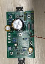
I am very new to the whole electronics-business, and chose to build "premium parts" version of the aca amp as one of my first soldering projects. After plugging it in, it unsurprisingly didn't work. One channel is getting hot, the other stays cold, neither is producing any audible output. I have started measuring resistances and voltages according to the troubleshooting diagrams in the build manual, but I am unsure whether the values also apply for this version. That thing, many values are off by quite a bit. One thing I did noticed and found weird is that the voltage going into R10 is much higher than the voltage coming out. The input value obviously depends on P1, but the output is somewhere in the 200-500 mV, in any case way lower than the expected voltage at the gate of Q1. Another thing is that the voltage on the middle pin of Q1 does not change when turning P1.
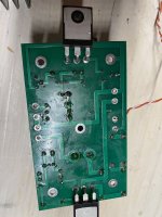
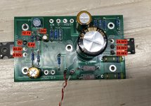
I checked most of the connections and could find a cold solder. I have no real idea what to check next, and unfortunately I have only access to two multimeters without diode testing. Testing the transistors is therefore possible, i guess, but I hope there are things I could check before getting into that. I have attached pictures of my mediocre soldering job and a few selected measurements, if this should be of any help. I realise that there could be quite a few issues here, so any help in narrowing down is greatly appreciated!
I checked most of the connections and could find a cold solder. I have no real idea what to check next, and unfortunately I have only access to two multimeters without diode testing. Testing the transistors is therefore possible, i guess, but I hope there are things I could check before getting into that. I have attached pictures of my mediocre soldering job and a few selected measurements, if this should be of any help. I realise that there could be quite a few issues here, so any help in narrowing down is greatly appreciated!
Attachments
I just built an ACA V1.8 and it sounds fantastic! I'm driving Omega Super Alnico High Output XRS (rated 4-6 ohms). I loved the ACA so much I decided to buy another and try running mono. Because the Omegas are rated 4-6ohms, I decided to try parallel mono but I found the image seemed compressed to the center and not as open as when I just run stereo. So I decided to try bridged mono.
What I'm finding in bridged mono is that my center image is shifted to one side (ie. one amp seems to be playing with more output than the other?). Here's what I've tried so far:
1. I switched left and right channel amps and the "lower output" amp remains the lower output (ie. the image shifts from left to right and vice verse when switching the amps).
2. I switched power supplies and no change.
3. I checked the DC balance voltages on both amps and they are all ~12V.
4. I checked solder points on the "low output" amp, reflowed a few connections but no dice.
5. Both amps seem fine in stereo mode.
Any suggestions on what to try next? Thanks!
Last edited:
After plugging it in, it unsurprisingly didn't work. One channel is getting hot, the other stays cold, neither is producing any audible output.
Working off pictures isn't easy
") but from what I can see there may be an issue around Q4.
but from what I can see there may be an issue around Q4.Can you check that R6 and R9 are correct. R9 must be 1k and you look to have a 1 ohm there (brown, black, black, silver and brown)
Good question. Short answer is no BUT...both amps seem fine in stereo mode and I would expect that if it was a source issue it would show up whether the amp was in stereo or monoblock, no?Just to make sure the problem is not upstream the power amps, did you also try swapping channels at the source- though ruling out source / pre / connexions?
I double checked and switched at the source with no change so I definitely think it's an issue with one of the amps. Is there a way to test the output to check for differences?Good question. Short answer is no BUT...both amps seem fine in stereo mode and I would expect that if it was a source issue it would show up whether the amp was in stereo or monoblock, no?
I'm assuming the problem is with the "lower output" amp so I'm focusing on that one. The left board reads R1= R2 = 345mV; R3 = R4 = 498 mV. The Right board reads R1 = R2 = 352 mV; R3 = R4 = 508mV.What is the DC voltage across the power resistors in the output stage?
I'm wondering if the issue could be at the selector switch? Maybe a bad solder joint there?
For the other amp (I'll call it the "higher output" amp) the readings are: left board reads R1= R2 = 353mV; R3 = R4 = 513 mV. The Right board reads R1 = R2 = 350 mV; R3 = R4 = 506mVAre those numbers the same for the other amp? or are they they same in all switch positions?
In both amps, the readings are the same in all switch positions.
Yes check the solderings and connections around the switch.I'm assuming the problem is with the "lower output" amp so I'm focusing on that one. The left board reads R1= R2 = 345mV; R3 = R4 = 498 mV. The Right board reads R1 = R2 = 352 mV; R3 = R4 = 508mV.
I'm wondering if the issue could be at the selector switch? Maybe a bad solder joint there?
Well, I double checked my switch soldering and tested continuity where appropriate as a double check. Double checked 12V on all 4 Q1s. Checked each board is getting 24V power. Hooked it all back up and still having same issue. One amp just seems slightly off in bridged mode and really pulls the center image to one side. I double checked my speaker connections and they are all good. Any ideas on where to look next?
The problem may be that only one side is working on the "Weak" amp when it is in the "RCA Bridged" mode. Check both sides are working by connecting speakers like the amp was connected in Stereo mode. The speakers will be out of phase, it's just a test to see if both sides are working.
- Home
- Amplifiers
- Pass Labs
- Amp Camp Amp - ACA