I am confused on how to trouble shoot.
Thanks
Voltage checks tell us much
")
All measured from ground and if possible use the correct terminology such as
Q1 Source=
Q1 Gate=
Q1 Drain=
and so on. There are only four transistors in each channel and so its only a moments work to not them all.
Or take a screen print of the circuit and write on it what you see.
ACA no sound
Thanks
Q1
D = 0 volts Assuming D is closest to the Q1 printed on the board
G = .2 mv
S = 18.02 volts
Q2
D = 106 mv Assuming D is closest to the Q2 printed on the board
G = 23.9 v
S = . 3 mv
Very odd and I have a working ACA here that I previously built. I tried to upload pics but not sure it worked.
Thanks
Thanks
Q1
D = 0 volts Assuming D is closest to the Q1 printed on the board
G = .2 mv
S = 18.02 volts
Q2
D = 106 mv Assuming D is closest to the Q2 printed on the board
G = 23.9 v
S = . 3 mv
Very odd and I have a working ACA here that I previously built. I tried to upload pics but not sure it worked.
Thanks
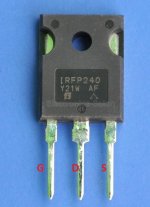
Pinouts are like this.
Lets take Q2 which is the upper FET on the ACA diagrams. The Drain (middle leg) must have supply voltage on it. So that looks to be what you think is the gate but check and confirm.
Not having ang gate voltage suggests a problem with R7 (open circuit or broken print) or a problem with a short from the gate to somewhere else.
So one step at a time.
1/ Check for 24v on the middle leg.
2/ Check for 24 volts on one end of R7.
3/ See what voltage is on the other end of R7. According to your readings it must be either 106mv or 0.3mv both of which would show a problem.
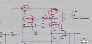
I'll post a diagram with typical voltages for you to compare.
Lets take Q2 which is the upper FET on the ACA diagrams. The Drain (middle leg) must have supply voltage on it. So that looks to be what you think is the gate but check and confirm.
Not having ang gate voltage suggests a problem with R7 (open circuit or broken print) or a problem with a short from the gate to somewhere else.
So one step at a time.
1/ Check for 24v on the middle leg.
2/ Check for 24 volts on one end of R7.
3/ See what voltage is on the other end of R7. According to your readings it must be either 106mv or 0.3mv both of which would show a problem.
I'll post a diagram with typical voltages for you to compare.
The R7 value is way off and I'm really struggling to think of anything that could cause that.
I can only think of scenarios where two or more errors exist. I think you need to look closely at the end of R7 that has the low voltage and confirm it connects only to the points it should.
One measurement that might give a clue but you need to be careful is to measure the voltage across R5. There should be absolutely no voltage showing across the resistor. That would give a clue where the current flows were occurring.
ACA no sound
Could it be that the resistor in the R7 slot is not the 10K ohm one? I am trying to test the resistance and not getting 6.5K ohms when I run the leads on it. If I switched the 10K resistor than I have more than one problem.
Not sure how I test voltage across R5.
Could it be that the resistor in the R7 slot is not the 10K ohm one? I am trying to test the resistance and not getting 6.5K ohms when I run the leads on it. If I switched the 10K resistor than I have more than one problem.
Not sure how I test voltage across R5.
I'll have to leave it for now but one thought seeing as both channels are seemingly the same is to check out of circuit that R7 is really a 10k.
Now pretty much any value should at least work (even a 100k, a 1meg or a 10meg) but if the resistor is open or more bizarrely is a cap (which can sometimes look and be marked like a resistor) then it would cause this fault.
So check R7 value out of circuit.
And when you measured the voltage on R7 I assume you measured to the leads themselves and not to where the leads go. You must measure on the lead itself of the part to eliminate the possibility of breaks in the print and so on.
Could it be that the resistor in the R7 slot is not the 10K ohm one? I am trying to test the resistance and not getting 6.5K ohms when I run the leads on it. If I switched the 10K resistor than I have more than one problem.
Not sure how I test voltage across R5.
Posted together
Lift one end of the resistor to isolate it and measure its value.
Measure across R5 by placing one meter lead on one end of the resistor and the other meter lead on the other end of the resistor.
I'll look in later.
Faults like this are always interesting but you must stick with a logical process. Its more than strange is this one
So the 10k is good and it has 24 volts on one end and essentially nothing on the other.
That means a current of 24/10000 is flowing in the resistor which is 2.4 milliamps. It can only go three ways, into a faulty or shorted C2 (but that on its own wouldn't give this fault) or into Q3 (and again that wouldn't cause this) or into R5... but then where?
The gate can't turn on until 4 volts or so are present... so it doesn't add up at this point.
2.4 milliamps in R5 would drop 0.0024*100 which is 0.24 volts. You measure just 0.2 millivolts. So we can say its not going that route.
Lets work the numbers the other way and see if that gives a clue.
To see 120 millivolts on R7 means a path of 50 ohms to ground exists. That's 0.12/0.0024= 50
And I can't see one
But you should measure resistance to ground from R7 and see if you read anything suspiciously low Make sure the amp is OFF.
I can only think up multiple fault scenarios that would do this. You would need a short from R7 to somewhere else, and that somewhere else in turn to be shorted to ground.
Both channels the same... it doesn't make sense.
You need to look and measure and see whether R7 is connected to anything else it should not be as a first step.
So its a mystery at this point. Visually check R7 connects only to C2, Q3 and R5. There should be no continuity to any other point.
Johnah, if you are both enjoying and learning from this process (I know I am!), you can take advantage of Molly’s teaching nature as well as his apparently endless patience.
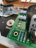
If you feel stuck, post good pictures of your boards and I can almost guarantee that whatever is wrong will surface faster. Still, I think your process has more merit and helps everyone learn more.
If you feel stuck, post good pictures of your boards and I can almost guarantee that whatever is wrong will surface faster. Still, I think your process has more merit and helps everyone learn more.
ACA no sound
F7 to ground one leg = 3.968 K ohms
other leg = 7.41 k ohms
Other board F7 leg to ground 3.44 K ohms
Other leg to ground 7.80K ohms
I figured out iphone was the issue attaching pics. How does 24 volts enter into one side of F7 and then die? Strange.
F7 to ground one leg = 3.968 K ohms
other leg = 7.41 k ohms
Other board F7 leg to ground 3.44 K ohms
Other leg to ground 7.80K ohms
I figured out iphone was the issue attaching pics. How does 24 volts enter into one side of F7 and then die? Strange.
Attachments
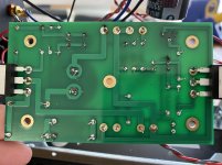
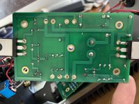
trim those parts legs shorter
reflow everything
proper/normal practice is to do all soldering from bottom side ....... except finishing elements , as legs of mosfets and some wires
just matter of procedure and logical checkup in later stage
measure suspicious resistors, compare with other channe4l ( if working)
if some part is suspicious ( reading) desolder one leg, pull it, remeasure
Hi jonah5
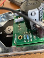
It very much looks as if you have Q3 and Q4 mixed up. The pictures are not too clear, but the ZTX450 transistor that fits in Q3 has two flat faces. Q4 K170 (the jfet) has one flat and one round face.
Compare to your working ACAs... or look here https://d17kynu4zpq5hy.cloudfront.net/igi/diyaudio/EinstNkNWRhq1sRF.full
Last edited:
- Home
- Amplifiers
- Pass Labs
- Amp Camp Amp - ACA