I built a second ACA (version 1.8) to go along with my ACA 1.6 (now modified to version 1.8). Everything seems to work fine except in measuring Mono RCA Bridged and Mono RCA Parallel I'm only getting slightly better performance than measuring one stereo channel. Is there something fundamentally wrong with the way I have the back panel wired or the way I'm measuring?
Attachments
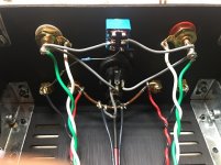
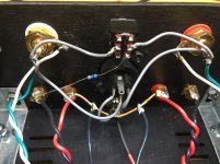
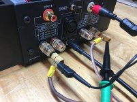
At a glance the back panel looks fine. Are you making the appropriate jumper connections for the speaker leads? When looking at the mono block RCA input, are you changing the speaker and measurement leads to the two outer posts (one on each channel) ? If not, you'd only be measuring one channel. So measure between the far outer black posts. There is no connection to the Red posts in that configuration.
B R R B
B R R B
Last edited:
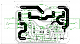
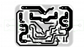
new 48vdc ACA, aka Kampana, new board layout......
Great stuff Tony.
Will you be offering the PCBs for sale?
I will be interested.
Keep up the good work.
They should be contacting you via PM shortly
No reply from diyaudiostore. Ill be headed to hardware store later today and zhopefully have this up and running later today or tomorrow. Will be using as a headphone amp for planars (Fostex T30 and TH500RP) direct from speaker taps. I dont have any very effecient speakers yet. Will do a FR BLH later.

Great stuff Tony.
Will you be offering the PCBs for sale?
I will be interested.
Keep up the good work.
all our boards are for local consumption, but let's see...if i can convince the board designer to give away gerbers.....stand by.....
Last edited:
So, do caps usually fail to open or a direct connection? If they usually fail open, then having 2 caps of half the value in parallel might give good protection…
Getting a touch of audio nervosa over the output caps, & my precious speakers. Has anyone ever had an output cap on the ACA fail? I do power cycle the ACA every time I use it. I have one of the speaker delay PCBs from diyaudiostore but, is that overkill?

There is no connection to the Red posts in that configuration.
Right! I've got an 8 ohm dummy load across speaker terminals (A-,B-). Scope probe attached at output A- and probe ground attached to B-. Wave form clips at about 2.5V input and about 8V output. That equates to about 8 watts.
Shouldn't I be able to push the output voltage to something like 11V?
Am I missing something here?
Attachments
Check this out. I think you are missing a jumper that joins the two - outputs together.
https://cdn.shopify.com/s/files/1/1006/5046/files/ACA_Monoblock_Operation_RevA.pdf
https://cdn.shopify.com/s/files/1/1006/5046/files/ACA_Monoblock_Operation_RevA.pdf
No reply from diyaudiostore. Ill be headed to hardware store later today and hopefully have this up and running later today or tomorrow. Will be using as a headphone amp for planars (Fostex T30 and TH500RP) direct from speaker taps. I dont have any very effecient speakers yet. Will do a FR BLH later.
Hi Philimon. The diyAudio Store Helpdesk is very sorry that your email was not replied to right away.
The store Helpdesk endeavours to reply within 48 hours to order errors but your email seems to have been mis-assigned. I apologise for that.
We will get the missing hardware to you soonest possible. We've sent you an email, kindly reply to that email or get in touch with us via contact@diyaudiostore.
Thank you.
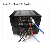
Sorry for the multiple replies - the paralell mono block mode ties the two negative posts together and you use one of those two and a positive post.
If I understand it all correctly: One way allows for more current for lower impedance loads. One allows for more voltage for higher impedance loads. My speakers which are rated at 4 ohms sound really nice when I use the parallel mono block mode in the picture.
So I guess to answer your initial question. You might measure the current as well as the voltage rather than just the voltage. Try it both ways and see which one is more sonically pleasing in your situation. There is a big difference in fidelity between the parallel and bridged for my speakers. Might be opposite in your case.
Check this out. I think you are missing a jumper that joins the two - outputs together.
https://cdn.shopify.com/s/files/1/1006/5046/files/ACA_Monoblock_Operation_RevA.pdf
I’ve seen that chart before as well but I believe that’s for version 1.6 only. My assumption is that the new switch and wiring of version 1.8 eliminate the need for this Y connector. I’ll go on to speculate that in version 1.8 (having the top two pins of the switch connected with a jumper) joins the right and left inputs together when the switch is in the up position.
i have been doing ss amps since the mid 70's, never had an output coupling cap fail, psu caps yes, there suffer from dry-ups with age/time due to esr heating...
and that is not surprising since psu caps have the rail voltages stored in them, the output coupling caps nothing dc, and even ac voltage drop is very small almost nil.....
and that is not surprising since psu caps have the rail voltages stored in them, the output coupling caps nothing dc, and even ac voltage drop is very small almost nil.....
- Home
- Amplifiers
- Pass Labs
- Amp Camp Amp - ACA