I wasn't much liking forced air cooling, it is always a good cooling option. One of the designs I had in mind was making a dual heat sink fins inward bolted with two flat plates into a square tunnel and a quiet fan running half speed pulling air from front to back.
It isn't the quietest option, but it makes the footprint smaller and forced cooling is efficient.
It isn't the quietest option, but it makes the footprint smaller and forced cooling is efficient.
Bob, for a rough approximation, divide your thermal rise by the power dissipation and that will provide you with the c/w rating of your current sinks.
Sounds good but I still need an assist. I'm assuming thermal rise is measured from ambient to operational at the junction of the power transistor. I'm not sure of the best place in this circuit to read the power dissipation.
Nichoch not sure what you are asking but will try...
First off I want to state that my join date here was before I made a cmoy or anything else...
( don't just go by what i say") many others here do know what they are doing....
many others here do know what they are doing....
The ACA works great, I have made 5 so far, it is my main headphone amp. The F5 does sound better but do not
like leaving it on all day or using that much power... am working on a smaller F5 with IRF520/9520's
With the speakers I have tried,,, Warfedale The F5 is leaps and bounds better.....
I have Fostex orthodynamic headphones rated at 3 watts....they need some power. So this amp seemed right to me.
the positive outputs are common with power supply ground and each other--- so tie them together not the negative outputs.....for normally wired headphone jacks.
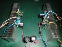
Loudthud has done a lot with other mosfets here and recomended I try the IRF520... So that is what is in the little one on right.. it works well even on 12v but I plan to try higher voltages and raise the bias a bit....to find the sweet spot..
so many projects going
I love these little amps, hats off to Nelson Pass for giving us his help, time and knowledge.....
First off I want to state that my join date here was before I made a cmoy or anything else...
( don't just go by what i say
many others here do know what they are doing....The ACA works great, I have made 5 so far, it is my main headphone amp. The F5 does sound better but do not
like leaving it on all day or using that much power... am working on a smaller F5 with IRF520/9520's
With the speakers I have tried,,, Warfedale The F5 is leaps and bounds better.....
I have Fostex orthodynamic headphones rated at 3 watts....they need some power. So this amp seemed right to me.
the positive outputs are common with power supply ground and each other--- so tie them together not the negative outputs.....for normally wired headphone jacks.
Loudthud has done a lot with other mosfets here and recomended I try the IRF520... So that is what is in the little one on right.. it works well even on 12v but I plan to try higher voltages and raise the bias a bit....to find the sweet spot..
so many projects going
I love these little amps, hats off to Nelson Pass for giving us his help, time and knowledge.....
Being Class A does their heat output really vary much with volume level?
From what I gather, I would think not as it is Class A and it is biased high above zero already (like the running temperature needs to be up when it is idling so the sound comes in "perfectly" without the ambient temperature needing to be reached). So to me it is always in a high voltage state.
Of course, I could be wrong.
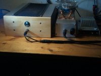
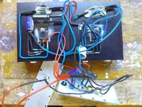
...just assembled AmpCampAmps last night. Thanks to NP, NBrock, Jason and fellow DIYers for design, papers, photo-instructions, kit and chassis ideas.....all superb! They are very easy to build, great sounding and quiet as a church mouse.
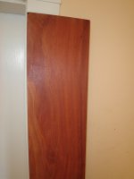
I'll finish a bloodwood chassis by the end of the summer and post finished photos then. For now, the amps and a plank of wood....
Mario
I'll finish a bloodwood chassis by the end of the summer and post finished photos then. For now, the amps and a plank of wood....
Mario
Attachments
Pass DIY Addict
Joined 2000
Paid Member
Sounds good but I still need an assist. I'm assuming thermal rise is measured from ambient to operational at the junction of the power transistor. I'm not sure of the best place in this circuit to read the power dissipation.
Sorry Bob, I should have provided more details. For thermal rise, use the highest temperature you can find on your heat sink (one of my meters has a tiny probe - I just put the probe on the head of the mosfet mounting bolt) and subtract off the ambient temperature. If you built a "stock" ACA, the power dissipation is 10w per transistor, so just divide temp rise by 10 (I'm remembering one CPU-style sink per transistor in your design). If both transistors are on the same sink, divide thermal rise by 20. I haven't read this entire thread or studied the article in great depth, so I don't know what changes in the circuit alter its bias point.
On another topic, were you able to rescue your toroid from a few months ago, or was the damage too extensive?
Eric
Last edited:
Pass DIY Addict
Joined 2000
Paid Member
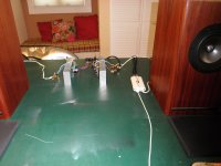
Mario - what speakers are we seeing your your photos above? They look like full-range. I'm looking for a very nice pair of full range speakers to go with an F4 or F5 with a DCB1 build. I'm thinking about Fostex 8", Mark Audio, TangBand 8", or Audio Nirvana. I haven't decided yet...
Eric, I'll stick my neck out and display my lack of knowledge in hopes it might also help others. I had the impression "power dissipation" referred to current/voltage differences or looses along the electrical path within the circuit. I checked a few sites but still came away with the same impression. I believe you are telling me the PD factor is a design element determined by the device manufacturer - a constant. Is that correct?
The process you describe is clear and understandable and I do have a temp probe for my meter. Just wanted to get some clarification on the dissipation thing.
No, I found a usable toroid in the stash for that application. I still have plans to try the repairs but haven't done it yet. Like everyone here - too many projects - so little time.
EDIT: Just saw post #1032 - Want to pass along that I listened to the ACAs pushing the Sunflower speakers all day yesterday. Those speakers are on the low efficiency side but it was a very enjoyable experience with the bare pot. Some selections were a little quiet but the sound quality was excellent. There is a wide range in studio recording levels and the more I played, the more I had to modify my opinion the ACAs are slightly under-powered. The pot was always at max but the composite/overall SPL was very acceptable and pleasant.
Last edited:
Eric,
Those are MarkAudio Alpair 10.2 in a TwinsAudio cab that I re-finished with veneer. They sound very nicely detailed with plenty of low end....especially so with the ACA. Madisound will soon carry the new MA A10.3 as well as a new A10P FYI.
The real surprise came when I first powered-up the amp after assembly. On advise, I hooked up some basic cheap Pioneer 2-way (SP-BS41-LR) as they're very robust and probably can't be blown up by most any amp. The combination was incredible for what these speakers are.....the best I've ever heard them.
But for detailed listening, its the MAs hands down. I think, depending upon your listening preferences, that you really can't go wrong with either the Alpairs or the less expensive CHR's from MA.
Mario
Pass DIY Addict
Joined 2000
Paid Member
Bob, in this context, I'm using power dissipation in reference to the actual power being run through the output mosfets. For a "stock" ACA without modification, each mosfet runs on a power supply that provides 20v and is biased at about 0.5 amp of current. In this case, Pd= v * I, or 20 * 0.5, or 10w. This is per MOSFET. There are two mosfets per channel, so 20w total dissipation per channel. For the ACA amp, I used the 2U sinks from the DIYAudio store. These exhibit a 18-19c rise over ambient while dissipating 20w (two transistors per sink). This reveals an approx rating for these sinks of 0.9 c/w each.
Typically, you can verify the bias point of your transistors by measuring the voltage drop across the resistor on the MOSFET source pin and divide it by the resistor value. In my Aleph-X amps, the source resistor is 0.333 ohms and I can measure a 0.5v drop across it. Thus, power dissipation per MOSFET is 0.5 / 0.333 or 1.5A. 1.5A times 22v power supply rails results in 33w dissipation. I have 12 output mosfets, so a total power dissipation of 396w. These amps exhibit a 35c rise over ambient, so the total sinking on each amp is 35/396 or about 0.088c/w for the completed chassis.
I just tried to do the same calculation on my daughter's ACA but the circuit is arranged differently, so I'm unsure how to calculate/measure bias in this amp. Perhaps someone else can chime in here, because we've hit the limits of my knowledge as well...
I keep hearing about the sunflower speakers - I'll have to give them a look!
Mario & Billy: thanks for the details on the Mark Audio drivers. I used the CHR-70s for my daughters system and find them to be very nice!
Pass DIY Addict
Joined 2000
Paid Member
Hello
Almost one year have gone by since I built my version of the ACA. Today I finished the last bits on one of the monoblocks and feel it´s worthy of showing to the community.
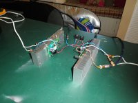
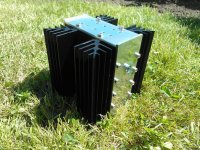
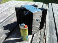
As can be seen, it has been built without any PCB and the components are held together by the mosfets and some "chewing gum" like adhesive. The construction consists of two 1,5 K/W heatsinks and some aluminum flat bar, held togheter by 20 screws (all drilled by hand). It can also be seen that I could not find big enough bias resistors so I just put 10 smaller resistors in parallell.
The amplifier is about 10 cm square but manages to produce a lot of good music for its size.
Almost one year have gone by since I built my version of the ACA. Today I finished the last bits on one of the monoblocks and feel it´s worthy of showing to the community.
As can be seen, it has been built without any PCB and the components are held together by the mosfets and some "chewing gum" like adhesive. The construction consists of two 1,5 K/W heatsinks and some aluminum flat bar, held togheter by 20 screws (all drilled by hand). It can also be seen that I could not find big enough bias resistors so I just put 10 smaller resistors in parallell.
The amplifier is about 10 cm square but manages to produce a lot of good music for its size.
Attachments
- Home
- Amplifiers
- Pass Labs
- Amp Camp Amp - ACA