If you still have doubts, from Papa Pass:
We will note that Common-Source operation intrinsically inverts the phase of the amplified
signal, and so we have reversed the polarity of the output terminals to account for that.
https://www.firstwatt.com/pdf/art_amp_camp_1.pdf
We will note that Common-Source operation intrinsically inverts the phase of the amplified
signal, and so we have reversed the polarity of the output terminals to account for that.
https://www.firstwatt.com/pdf/art_amp_camp_1.pdf
..J FET selection
Hi
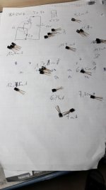
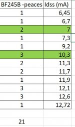
i checked the Id current from my BF245B N-JFET.
the current is about 6 to 12mA..so i have to choose the 2 pcs with 7mA...right?
Hi
i checked the Id current from my BF245B N-JFET.
the current is about 6 to 12mA..so i have to choose the 2 pcs with 7mA...right?
Attachments
Last edited:
Should be good. Lower Idss on your list are more suitable for the ACA compared to the higher ones, better temperature feedback for bias stability.the current is about 6 to 12mA..so i have to choose the 2 pcs with 7mA...right?
Should be good. Lower Idss on your list are more suitable for the ACA compared to the higher ones, better temperature feedback for bias stability.
i thought that the temp feedback is done by R9?...no?
Sorry, bad wording. Given a fixed vgs a mosfet will bias at a current that will be dependent on temperature. Voltage divider formed by P1 in ACA also works as feedback stabilizing variation of output stage DC bias current vs temperature. Lower Idss Q4 will result in better feedback action vs temperature. On the contrary, early clipping will happen if Idss is too low.
Last edited:
Hi,
I am hoping to start building monoblocks tomorrow, waiting for new tips for my welder. In any case two question. What do you guys think of pairing the ACA mini blocks with the Schiit Valhalla Preamp and Focal Chora 826 speakers. The Focal are 91db efficient but their specs recommend from 25 watts for channel. The room these will eventually go into is about 15 x15 or 225 sq. Ft. I do now and then rock out but generally I listen to softer rock, jazz and classic.
Any ideas?
Thanks,
J
Yeah the ACA circuitry inverts the signal. Nelson doesn't like that. I believe he had an associate who could identify whether the phase was inverted or not in a blind test by just listening.
So it's simple to fix by making the positive outputs go to the black terminal and the negative (ground) from each of the channels to the appropriate black terminal. Since the red terminals are actually ground now, they can be connected together. Since the black terminals are now the positive, they have to be kept apart for 2 channel operation.
The amp is so easy to build, that this one issue causes about half of all the confusion and questions about construction.
When I was designing the new V1.8 rear switch to select the various monoblock options, I also got confused and the text on the rear panel had to be revised!
Ben - I did read the build guide. The question was to confirm what I saw there... Your explanation that the amp output phase is inverted and therefore +OUT goes to GND now makes more sense, I guess
Thanks!!
Last edited:
Unfortunately, given that there is no standard for phase on the software we listen to, the artifical swapping of the speaker terminals is only a cosmetic bandaid as one still has to figure out the absolute phase of the recording (if it is consistent, your system and ears ar eup to detecting it).
Unfortunately i did not get to Chris soon enuff to have the terminals installed with black to ground. I am still tempted to go in and fix that. I also used different binding posts than supplied with mine.
I find the backwards posts “confusing”.
dave
Unfortunately i did not get to Chris soon enuff to have the terminals installed with black to ground. I am still tempted to go in and fix that. I also used different binding posts than supplied with mine.
I find the backwards posts “confusing”.
dave
amp powers down, then back up
hello all a little help would be very appreciated
just build v1.8
the amp will play for about 45 seconds, then power itself down for about 2 seconds, then back up.
Does it regardless if music going thru it or not.
When it powers up/down, it makes a sound like my speakers are farting.
thanks!
hello all a little help would be very appreciated
just build v1.8
the amp will play for about 45 seconds, then power itself down for about 2 seconds, then back up.
Does it regardless if music going thru it or not.
When it powers up/down, it makes a sound like my speakers are farting.
thanks!
been there done that.....it is entirely doable...
Nice!!
The only thing is.... i do not have a source with a balanced output (yet)
hello all a little help would be very appreciated
just build v1.8
the amp will play for about 45 seconds, then power itself down for about 2 seconds, then back up.
Does it regardless if music going thru it or not.
When it powers up/down, it makes a sound like my speakers are farting.
thanks!
did you tried another PSU?
counting that you did check few voltage points in amp, so amp is set as needed?
Thank you for your detailed answer. I would like to build a stereo amp using 4 ‘aca modules’ and they’d be in bridged mode. I’d like to have both balanced as rca inputs, so depending on the source, I can choose which input I use (why limit my options") ), but I now realise I need a switch to choose, which is fine.
), but I now realise I need a switch to choose, which is fine.
Cheers,
Neel_007
), but I now realise I need a switch to choose, which is fine.Cheers,
Neel_007
Do you need to operate 4 speakers/4 channels and/or are you using a balanced source and want to have monoblocks for 2 channels? Do you have a single-ended source with only RCA outputs and still want to bridge the amps?
You would want the switch if you ever wanted to bridge the amps using a single-ended source and use an RCA connection. If you only intend to use it with a balanced source through XLR as a monoblock or stereo RCA, then no. Either way, if you chose to wire it w/o a switch, then you will not want it wired in the "switch up" position. You will want it wired like the "switch down" position.
Short answer, maybe...???? But I wouldn't. Why?
See the wiring guide for 1.6 step 33. You would be:
- feeding the inverted signal from pin 3 through one amp board
- the signal would be amplified and phase inverted to positive phase and the signal would include the distortion from the amplification
- the voltage would be reduced through the 39k resistor,
- then it would be combined with the "non-distorted" positive phase input from pin 2 and amplified through the other amp board to which you would hook up your speaker.
If you wired your speaker properly to just that amp board (NOT like you would for 'Normal' XLR bridged operation), it probably would not hurt anything. I'm not sure how that would sound. Also, you'd be feeding the signal at 'double' the voltage to one amp board. Depending on the level, you'd probably clip much more easily.
Someone else should proof this for accuracy to be certain. I could be way off, but there's a small chance I have some of it correct.
Edited to add: See above for a much more simple answer. I type too slowly.
hello all a little help would be very appreciated
just build v1.8
the amp will play for about 45 seconds, then power itself down for about 2 seconds, then back up.
Does it regardless if music going thru it or not.
When it powers up/down, it makes a sound like my speakers are farting.
thanks!
You need to measure the total current draw of your ACA and see whether it is exceeding the limits of your power supply.
Are you using the recommended Meanwell PSU?
One channel of the ACA running on 24 volts DC should draw around 1.6 A, so around 3.2 A for a stereo pair.
hello all a little help would be very appreciated
just build v1.8
the amp will play for about 45 seconds, then power itself down for about 2 seconds, then back up.
Does it regardless if music going thru it or not.
When it powers up/down, it makes a sound like my speakers are farting.
thanks!
wait before playing music, the cap C1 is charging up during power on ---feeep ........and discharge during power down - pop sound -that is normal
with power level is you psu? voltage and amps?
Hi Mooly
i follow your instruction:
here are some pics/measurements about my R channel with 24V supply and just this channel was connected, means RCA just at R ch, load 4R at R channel, L channel completely disconnected.
finally i got after my 4A fuse at the amp and connections 23,82V at the amp board.
bias is 1,57A and AP is 11,20V
pic 1 Rchannel Supply 23,82_1500mvrms
pic 2 Rchannel Supply at _23,82_1540mvrms
compared to the L channel
pic 3 +4
i am thinking that at this clone pcb this strange diode is doing something strange...
pic 5 left buttom corner FR207 no idea what this diode is doing...
Hi I bought te same board - with components. I have small channel imbalances, in AC, you have big.
- the feedback resistors could be different between channels.
As regards the power shutting down; thermal protection of PS kicks in probabbly. You need an overhead in the supply; with 2x1,5A, you need 6-10 amps specs.
I have current imbalances, that I tried to overcome with changing the drain/source resistors. I cannot get it totally the same.
I have thought the output FETs are not equal. Not matched. Maybe same inprint but oh my a whole other FET all together

By the way I use it for a headphone, so @ 140mA (ch A) /150mA (B) less current by intent.
We all know how they keep the prices low. They buy factory rejects and so on . .
So better: in doubt, replace the output fets with some from a reliable source. But with the feedback, the AC should be similar.
Last edited:
Hi triode
Yes i did some failures about the components at the beginning..remember 1k instead of 10k...wrong sorted...however.
at this clone pcb i measured the components but i have to try with "real" components. actually my time is hardly reduced now for audio.
pleas do not use the diode at the place of FR207. its in the Drain of the N-JFET and its useless in my opinion. the sound is then super smooth and wooly..much better without. if i do a self review of my ACA i have the problem of power my 4R speakers with 85dB and this is not the best solution for ACA. Therefore i think i get quicker the H2 clipping sound as others members-especially with my un symmetrical DC Biasing of 9,1V. actually its sounding really fine. the Q2 get about 90°C and this not a nice setup.
I only use the N-JET, MOSFET IRFP240 and some resistors from this seller.
R9 for example is not 1k...1k5 i my case maybe better because of the lower current by the K30A N JFET. i need more time to recheck everything and setup the DC bias about 1/2 the supply ! sound is still very nice...
As a read nearly 470 pages of this thread i found a comment by ZEN mod that nobody fake the IRFP240 MOSEFET...and i belive he is right...there is no need. its a cheap and robust component.
chris
Yes i did some failures about the components at the beginning..remember 1k instead of 10k...wrong sorted
...however.at this clone pcb i measured the components but i have to try with "real" components. actually my time is hardly reduced now for audio.
pleas do not use the diode at the place of FR207. its in the Drain of the N-JFET and its useless in my opinion. the sound is then super smooth and wooly
..much better without. if i do a self review of my ACA i have the problem of power my 4R speakers with 85dB and this is not the best solution for ACA. Therefore i think i get quicker the H2 clipping sound as others members-especially with my un symmetrical DC Biasing of 9,1V. actually its sounding really fine. the Q2 get about 90°C and this not a nice setup.I only use the N-JET, MOSFET IRFP240 and some resistors from this seller.
R9 for example is not 1k...1k5 i my case maybe better because of the lower current by the K30A N JFET. i need more time to recheck everything and setup the DC bias about 1/2 the supply ! sound is still very nice...
As a read nearly 470 pages of this thread i found a comment by ZEN mod that nobody fake the IRFP240 MOSEFET...and i belive he is right...there is no need. its a cheap and robust component.
chris
- Home
- Amplifiers
- Pass Labs
- Amp Camp Amp - ACA