fred0 - see http://www.diyaudio.com/forums/pass-labs/215392-amp-camp-amp-aca-508.html#post5509597
for more details. Back switch, is this case, is used for bridging with the RCA inputs. Front switch is used for power off/on.
OMG
This is my solution presented in a for dummies diy be monkey and dont fu*** up kind of thing - so as long as i mimic these i will have all correct.
\o/
Rafapolit, the noise I get is significantly louder than you're describing. But I guess it's OK. I'm using the 24v version.
This amp does get very hot. I biased to 12v as per instruction. I can keep my hands on the heat sink (using posh v1. 6kit enclosure) but any hotter and I probably woundnt. It's quite a bit hotter than my f4 gets.
This amp does get very hot. I biased to 12v as per instruction. I can keep my hands on the heat sink (using posh v1. 6kit enclosure) but any hotter and I probably woundnt. It's quite a bit hotter than my f4 gets.
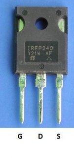
That changes things a bit then... its also much easier to follow if you use the Gate (G) Drain (D) and Source (S) terminology. If your unfamiliar with the component and component markings then I know it takes a bit of getting used to ")
So then... if pin 3 (the Source) of FET Q2 has 24 volts on it then that voltage should be present on all four resistors (R1, R2, R3 and R4) and from there onto Q1 Drain.
That is the next thing to check then. That you have 24 volts on each end of each of those resistors. No need to record the voltages, the voltage will either be there or not. If you have 24 volts on one end of a resistor and nothing on the other then the resistor has failed open (due to some underlying fault).
Another anomaly is pin 1 (Gate) having almost no voltage... a few possibilities yet though.
fred0,
Your Pre Amp looks great, and it has all RCA connectors for audio. That is true for most of these AV-type components. Its perfectly fine. You don't have XLR connectors, nor balanced audio at all.
For short, balanced audio uses two wires to carry the signal, one inverted to the other. The signal itself is inverted, but common noise like hum or radio frequencies is the same on both wires (it is not inverted). So the idea is that, when you reconstruct the audio, you only use whatever is 'opposite' on both signals, and discard what is common, therefore ending up with a cleaner signal.
Since you only have one ACA Amp, all the 'mono' features like the XLR and the Single-Ended mono RCA configuration would be of little use to you (as is my case). So don't worry much about them. 6L6s guide for the front switch is coming really soon, and everything will be really clear once you get those pictures.
Maybe that depends on the sensitivity of the speakers? But yeah, its the same scenario.Rafapolit, the noise I get is significantly louder than you're describing. But I guess it's OK. I'm using the 24v version.
This amp does get very hot. I biased to 12v as per instruction. I can keep my hands on the heat sink (using posh v1. 6kit enclosure) but any hotter and I probably woundnt. It's quite a bit hotter than my f4 gets.
Mine get hotter than what you describe.
You have an F4? You built it yourself? Or is it FirstWatt stock? How would you compare the sound from that to the ACA? I'm curious.
Best regards,
Rafa.
We have to be more sure yet by doing voltage checks. You are saying you have 24 volts on the Drain and Source of Q2 and yet no voltage on Q1. I'm asking you to check the resistor voltages as a double confirmation of your results. Those low value resistor could not support 24 volts across them if they are OK, they would be red hot and smoking if the power supply didn't shut down first.
You should find at least one parallel pair of those resistors is open circuit to corroborate the reading you gave. Its all about checking and confirming the results before jumping in and randomly replacing parts.
This is the pin out of the IRF240 transistor.
You should find at least one parallel pair of those resistors is open circuit to corroborate the reading you gave. Its all about checking and confirming the results before jumping in and randomly replacing parts.
This is the pin out of the IRF240 transistor.
Attachments
Rafa, the Missions are about 89db ish so not desperately sensitive.
Yes, built the f4, impasse, his masters noise and the obl15 speakers.
The aca has a lot in common with the f4 sound wise. It has a characteristic liquid sound. However the f4 does sound tighter and more focused, less distortion and a more balanced sound. But essentially they are similar, the f4 was a bit like an aca with a very serious steroid injection.
... But essentially they are similar, the f4 was a bit like an aca with a very serious steroid injection.
The difference between an SET output stage with a low damping factor and more 2nd harmonic and a push pull complementary output stage with a much higher damping factor and more 3rd harmonic...
Best,
Anand.
Suddenly, it is biasing and set it up at 11.7+ on both boards. What a surprise. I measured resistors 1 2 3 4 and all have at least 7+v. I will hook it up and take a listen. Again Thanks for now and I will post what will happen.
I would go through and resolder/retouch any connection on the board. Might be a bad solder joint that will cause intermittent issues. It happened to me with my ACA and I've been DIY-ing for almost 30 years!
Hi anand, I did wonder if the set output and low damping factor had something to do with it. I think I'll try putting in my main system just to see what it's like with a better dac and speakers. Then I can get a better idea of the difference. But it's good to know that the super low damping factor isn't so much of a detriment. I've been thing of building a second f4 to run balanced and that half's the df to 20. Although I suspect I'll want to biamp.
I checked everything:
- that there is no shorts anywhere
- that MOSFETs are not shorted against the heatsink (middle leg should not beep continuity with the heatsink)
- I actually measured every expected value on their 'next' points... so I measured a resistor one 'hole' ahead and one hole before to make sure everything was properly soldered and with their correct values (which I did measure beforehand as well)
- make a final visual inspection that every cap and transistor is oriented correctly (I had one soldered the other way around)
Be sure to first power up the amp without any input source or speakers! Once you start it up, I tried to quickly assess that the bias current is not beyond the 12V mark. And then, just work slowly.
That's about it!
We have to be more sure yet by doing voltage checks. You are saying you have 24 volts on the Drain and Source of Q2 and yet no voltage on Q1. I'm asking you to check the resistor voltages as a double confirmation of your results. Those low value resistor could not support 24 volts across them if they are OK, they would be red hot and smoking if the power supply didn't shut down first.
You should find at least one parallel pair of those resistors is open circuit to corroborate the reading you gave. Its all about checking and confirming the results before jumping in and randomly replacing parts.
This is the pin out of the IRF240 transistor.
Let me just report to you the S now measures about 12.+ v so are resistors 1 2 3 & 4 all ends. Resistors 3 & 4 are a little lower at 11.6 v. on the other ends.
However, there is no sound coming when connected to a speaker.
The other board also measures similarly and there is sound coming out.
I would go through and resolder/retouch any connection on the board. Might be a bad solder joint that will cause intermittent issues. It happened to me with my ACA and I've been DIY-ing for almost 30 years!
I did what you recommended and all related measurements were now at what mooly told me to be so if I understand him correctly.
However there is no sound coming out on this channel. The other one has.
It looks like another problem.
Thanks for your help.
Last edited by a moderator:
- Home
- Amplifiers
- Pass Labs
- Amp Camp Amp - ACA