Ok, I've adapted this pot to simulate a true single-channel pot. Now, any output load & any input load is usable. Also, a volume of 0 is now - (infinity) db. 127 will be -0.000000 db.
I've boxed the DPDT relays. The top half is wired to the n-o (normally open) side, and the bottom is on the n-c (normally closed).
I know it's double the resistors & double the switches, but, I want an authentic emulation of a real logarithmic pot.
Will it emulate correctly?
I've boxed the DPDT relays. The top half is wired to the n-o (normally open) side, and the bottom is on the n-c (normally closed).
I know it's double the resistors & double the switches, but, I want an authentic emulation of a real logarithmic pot.
Will it emulate correctly?
Attachments
Brian Guralnick said:It was mentioned on another link to this attenuator that it was patented. Whats the US patent #?
It is NOT patented - only copyrighted
") . I did publish it in 2002 to prevent someone else from doing it as it is in a public domain now. The question was about your design not mine - I think it was something on patent pending on one of your diagrams?
. I did publish it in 2002 to prevent someone else from doing it as it is in a public domain now. The question was about your design not mine - I think it was something on patent pending on one of your diagrams?x-pro.
Kay said:"this circuit is copyright of Creek Audio Limited, however it is already in a public domain for more than a year and half. "
Really?
I saw the circuit first at ELEKTOR 1991/7-8, page 23.
I post this circuit at July on
http://www.audiodiskussion.de/foren/selbstbau/msg.php?idx=37117
That is a different circuit, though a similar idea
. I used only ONE switchover relay contact where that circuit uses two, as would be required for T or P -attenuators as well.x-pro.
Re: Re: Constant impedance relay-resistor logarithmic attenuator
You can drive it with any source impedance, however it will introduce an additional (but constant) attenuation. It needs to be loaded on 10 K, and if your load is higher impedance you may add some resistor in parallel to it to make it closer to 10K. Strictly speaking that somewhat lower load impedance, i.e. 5K would only introduce some noticable error for first 10-15 dB of attenuation. In practice it would be quite acceptable. I did use it as a passive device without much of a problem.
x-pro
Brian Guralnick said:
In the magazine schematic, your input impedance is listed with 10k input impedance. Does this mean I should drive the attenuator with a 0 ohm drive & expect the load of the attenuator to be 10kohm?
What's the level of affect on this attenuator as the output load changes? For example, if I make 2 driving 2 amps, and 1 amp has a load of 10.1k, and the other 9.9k, how messed up will the balance be?
I guess if the output load is unknown, this circuit should have an added output buffer. Sort of kills the ability to use this circuit externally as a passive device.
RF guys done this to match signal lengths & number of resistive elements as the relays are switched.
This is the 1 main beef I have about this circuit.
In my attenuator, the signal being fed through always appears to have 8 switches closed & another 8 open, it also appears that there are always 8 resistors in the signal path.
My final schematic makes this fairly easy to see:
http://pages.infinit.net/helloftp/attschemnew.png
Except now, I need to work out a log version.
You can drive it with any source impedance, however it will introduce an additional (but constant) attenuation. It needs to be loaded on 10 K, and if your load is higher impedance you may add some resistor in parallel to it to make it closer to 10K. Strictly speaking that somewhat lower load impedance, i.e. 5K would only introduce some noticable error for first 10-15 dB of attenuation. In practice it would be quite acceptable. I did use it as a passive device without much of a problem.
x-pro
Brian Guralnick said:Ok, I've adapted this pot to simulate a true single-channel pot. Now, any output load & any input load is usable. Also, a volume of 0 is now - (infinity) db. 127 will be -0.000000 db.
I've boxed the DPDT relays. The top half is wired to the n-o (normally open) side, and the bottom is on the n-c (normally closed).
I know it's double the resistors & double the switches, but, I want an authentic emulation of a real logarithmic pot.
Will it emulate correctly?
My circuit in a first message IS a correct emulation of a log pot. If you want a balanced version you wire two in parallel - one for "hot", one for "cold" input and take two outputs as well. Your idea on that diagram is not quite clear to me
. However it would make sense (and I've done it in production) to wire the relays in "max" attenuation position when there is no power to the relays (opposite to what is shown on the diagram from the magazine). x-pro
There is a little problem with this circuit, the input impedance is really 10kOhms (if there is a 10k on the output too), but output impedance is changing with the actual relay-settings !!! So it's better to use pi or T-network, if you don't want to compute values of resistors and parallel or serial combinations, you can read something about it and use applet from my page, but it's only in Czech language. Have a nice day with a dictionary
http://dzin.hi-end.org/utlum.htm
Dzin
http://dzin.hi-end.org/utlum.htm
Dzin

x-pro said:
My circuit in a first message IS a correct emulation of a log pot. If you want a balanced version you wire two in parallel - one for "hot", one for "cold" input and take two outputs as well. Your idea on that diagram is not quite clear to me
x-pro
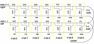
This is what my circuit does. I wired 2 of your pot's, back-to-back, 1 upside down, in parallel, taking the attenuation point from the middle.
(To make it clear, I'm not talking about XLR Balanced, from here on in, Im talking about a single, mono, 1 channel pot.)
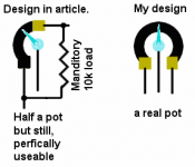
Your pot only emulates the left hand side of a log pot, this is why it needs an output load. See attached illustration, hope my art isn't too bad & I got it right.
Attachments
A bit off-topic, but...
There is no such thing as a copyright on a circuit. You can hold a copyright on texts, pictures and diagrams of a circuit, but this stops noone from drawing their own diagrams and using the circuit for whatever they like.
I don't think the circuit in the first post could be patented. Too many very similar designs have been around for quite some time.
The "intellectual property" thread is a very interesting read: http://www.diyaudio.com/forums/showthread.php?s=&threadid=20960
Laws are different in different countries, and what I said applies to Germany and I guess to most other countries, too.
x-pro said:It is NOT patented - only copyrighted
There is no such thing as a copyright on a circuit. You can hold a copyright on texts, pictures and diagrams of a circuit, but this stops noone from drawing their own diagrams and using the circuit for whatever they like.
I don't think the circuit in the first post could be patented. Too many very similar designs have been around for quite some time.
The "intellectual property" thread is a very interesting read: http://www.diyaudio.com/forums/showthread.php?s=&threadid=20960
Laws are different in different countries, and what I said applies to Germany and I guess to most other countries, too.
Kay said:>I used only ONE switchover relay contact
Yeah, I see,
it will be better to minimize the relay contacts in signal path!
This isn't always true, in the example diagram, your source alway goes through a mixed chain of different lengths. In the audio spectrum, this shouldnt be a problem, but, in high frequence, the changes of the input characteristics may have a slight affect on the source's driver.
OK, which 1 is correct?
A, or B.
It is understood that the switch positions on the right hand side of the Actuator are inverted to the ones on the left, changing the same -db # switch on each side at the same time as 1 bit.
Also, now, only the ' Min / Actuator / Max ' make up the 3 external conections available on a normal pot. The bottom trace is only internal now.
Right???
Attachments
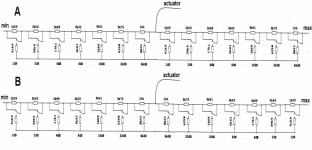
My battery powered attenuator is identicle to the 'B' version in my last post, I'm only missing the bottom trace with it's resistors. I'm adding that bottom trace & it's resistors right now. Version 'B' seems to visualize correctly for me.
My goal is to make a log attenuator with -128db attenuation in 256 x 0.5db steps.
My goal is to make a log attenuator with -128db attenuation in 256 x 0.5db steps.
To calcualte such a circuit you have to deside on what load you need.
If you want a potentiometer of 47K lets say like a real one then you must start with a load resistor of 47 KOhm.
This will be called Rload.
The resistors in series with the signal will be called RXn (n= 1,2,3,4.....) and the resistors to ground will be called RYn (n= 1,2,3,4.....) N depends on how many pieces you have on the chain. Practicle would be to have 8 while using a digital control with 8 bits. n=1 for -0,5 dB, n=2 for -1dB, n=3 for -2db, n=4 for -4dB till n=8 for -64dB. This attenuator will have a total of 256 steps with max attenuation -127,5 dB.
For this circuit to function each RYn resistor must be so calculated that in parallel with Rload plus RXn should be equal to Rload again. Thia means no matter what the connections the load is always equal to Rload.
To start you must calculate the attenuation you need as a number and not in decibels. you can do this by using a calculator with log and antilog function. The antilog function is usualy marker as 10 power x.
-0,5dB is 0,944 output 1 would be odB
Each RYn is RYn=A / (1-A) x Rload
For 47KOhm and for the first part -0,5dB RY1 is 2,63K
Each RXn is RXn=(1-A) x Rload
RX1 is 792KOhm
To prove that the load remains constant we can calculate it.
RX1 is parallel to Rload. Together they make an RZ. This equals to
RZ=Rload x RX1 / (Rload+RX1)= 792K x 47k / (792K + 47K) =
37224 K² / 839 K = 44,37 KOhm
the new load would be this RZ + RY1 = 44,37KOhm + 2,63KOhm = 47KOhm
- Status
- This old topic is closed. If you want to reopen this topic, contact a moderator using the "Report Post" button.
- Home
- Amplifiers
- Pass Labs
- Constant impedance relay-resistor logarithmic attenuator