It looks genuine to me. It's from an older production run and cut-tape.
I bought 50pcs of 2SK170, but when I look at my trusted local store, I just find out 2 strange things : bad printing and the legs shape. Some diy'ers on the store said for sure that it's FAKE. and it's about 50 FAKE trans, wew
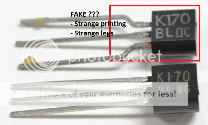
below figure for what I get from my trusted local store, and it's the same as my α20 trans kit from amb.org
k170/j74 discontinued,what can instead it?
k366/107 or k246/j103 or k389/jxx
K170/J74 are quite hard to get and expensive, so I was thinking of using K389/J109 instead because I have two pairs of them.
What is going to happen if I convert the F5's front-end like this one using K389/J109 with or without C1775/A872?
Attachments
There's something wrong !K170/J74 are quite hard to get and expensive, so I was thinking of using K389/J109 instead because I have two pairs of them.
What is going to happen if I convert the F5's front-end like this one using K389/J109 with or without C1775/A872?
The 100rVR has a short across it.
Is that circuit from a reliable source?
389/109 are 170/74 , double die
JFets on that schematic must be cascoded , due to rail voltages involved
if you read F5T article , everything is explained there - when and how to cascode (or not)
Sure, if I am going to actually use 389/109 with 24V rail of F5, I will remove the cascode.
What do you think about the differential topology of 389/109? Will it work with F5? To my understanding level, it will, but since I am no expert...
There's something wrong !
The 100rVR has a short across it.
Is that circuit from a reliable source?
It is basically designed by a renowned Japanese audio reviewer and designer,
Kubota Takashi
His favorite style is (although not always used):
- No NFB from the speaker output
- FET
- K389/J109 pair for input
- Regulated PSU for input/VAS, unregulated for output
- Simple is better approach
His work has been published on Japanese audio/diy magazine MJ, as can be seen here:
MOS-FET AMP - ???? - Audio ??? - Yahoo!???
Some critics that his symmetric design has too much odd number distortion.
What do you think about his circuits? It looks like they were very popular in Asian countries in 80's and 90's.
Sure, if I am going to actually use 389/109 with 24V rail of F5, I will remove the cascode.
What do you think about the differential topology of 389/109? Will it work with F5? To my understanding level, it will, but since I am no expert...
you can either put them in parallel , having iteration of F5 with slightly greater OLG etc. , but if you use that differential topology .... that's another amp
It is basically designed by a renowned Japanese audio reviewer and designer,
Kubota Takashi
His favorite style is (although not always used):
- No NFB from the speaker output
- FET
- K389/J109 pair for input
- Regulated PSU for input/VAS, unregulated for output
- Simple is better approach
His work has been published on Japanese audio/diy magazine MJ, as can be seen here:
MOS-FET AMP - ???? - Audio ??? - Yahoo!???
Some critics that his symmetric design has too much odd number distortion.
What do you think about his circuits? It looks like they were very popular in Asian countries in 80's and 90's.
part of history ...... and good today also
well known to anyone serious about amplifier design
K170/J74 are quite hard to get and expensive, so I was thinking of using K389/J109 instead because I have two pairs of them.
What is going to happen if I convert the F5's front-end like this one using K389/J109 with or without C1775/A872?
So I simulated F5 with K389/J109 differential front end using LTSPICE.
Basically I could achieve similar output characteristics but with more carefully feedback. I think it is because feedback is fed by one of K170/J74 in the K389/109, which is different from feedback fed into the source resistor in F5.
")
Better to use them to build the F5X.
Patrick
That's a great suggestion. Excuse my ignorance, balanced configuration is similar to bridging, so each output sees half of the load? Like seeing 4 ohms from 8 ohm speakers?
Thanks,
Doug
- Status
- This old topic is closed. If you want to reopen this topic, contact a moderator using the "Report Post" button.
- Home
- Amplifiers
- Pass Labs
- What can I use instead of k170/j74?