Will depend on inductance of the resistors, umut.
The only way to work out what you need is to construct the circuit in a simulator, put in measured inductance values, and run high level 50kHz square waves into the sim.
With the correct capacitor value has been reached you will see no ringing at the output, and no oscillation. If it is too high the output resembles a sine wave and if it too low you will see peaks.
The feedback compensation is simply a cap across each of the feedback resistors. The source compensation is more tricky, a capacitor from drain to gate is what we normally use. If your resistors are extremely inductive, you might need a resistor in series with the capacitor(s) to damp the circuit.
You'll be in a bit of unknown territory, nobody has built this circuit with inductive resistors. I did, and I ended up throwing them away and replacing them with the metal plate resistor type.
inductance of resistors
Hi.As i remember i measured dale rs-2 resistors inductance and a non inductive pilkor mox resistors inductance by DER EE DE5000 LCR meter for my friends amplifier and there was not any difference between them (values were around 0R33 ) .Will also check 100R resistors inductance.
Hi.As i remember i measured dale rs-2 resistors inductance and a non inductive pilkor mox resistors inductance by DER EE DE5000 LCR meter for my friends amplifier and there was not any difference between them (values were around 0R33 ) .Will also check 100R resistors inductance.
Yes. I've been around, just not posting much except in subscribed threads.
umut, if the resistors are not inductive additional compensation will not be needed. You might, depending on your layout and other issues, still need feedback compensation, about 1nF is recommended though I've built with as low as 220pF and had no issues long-term (8 years now).
umut, if the resistors are not inductive additional compensation will not be needed. You might, depending on your layout and other issues, still need feedback compensation, about 1nF is recommended though I've built with as low as 220pF and had no issues long-term (8 years now).
You don’t need to go to 800va for a 50w V2. 600 would be plenty.
OK, so this one? AN-6225 - 600VA 25V Transformer - AnTek Products Corp
Yes.
Thanks. What are we using for power and signal wire? I was looking at the 16g stranded at Apex Jr. I want a clean color-coded build.
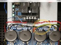
Hi, i have hum problem with my F5T. It's not very loud, but it can be noticed from listening position.
For now i tried to lift the safety ground but with no improvement. If i short the input it is almost dead quiet.
Any idea where to start?
For now i tried to lift the safety ground but with no improvement. If i short the input it is almost dead quiet.
Any idea where to start?
Attachments
to a007udio #6592
Hello a007udio,
do you have the possibility to change your preamp or the source?
Only to be sure, that the hum isn't induced by a stage before the F5T.
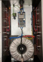
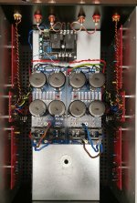
Your F5T-build looks very good!
The AC-lines are well twisted but running directly over the toroid. This
could be a scenario that you get problems/ hum there?
I assume it is 50 Hz-hum?
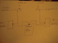
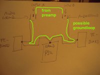
Possible groundloop over the RCA - input A - to the frontendboards - to RCA-input B? I think about that, because if you short the inputs it is dead quiet?
Only some thoughts....
Cheers
Dirk
Hello a007udio,
do you have the possibility to change your preamp or the source?
Only to be sure, that the hum isn't induced by a stage before the F5T.
Your F5T-build looks very good!
The AC-lines are well twisted but running directly over the toroid. This
could be a scenario that you get problems/ hum there?
I assume it is 50 Hz-hum?
Possible groundloop over the RCA - input A - to the frontendboards - to RCA-input B? I think about that, because if you short the inputs it is dead quiet?
Only some thoughts....
Cheers
Dirk
Let’s try a starground.
Connect all your grounds here.
Both channels PSU GND to the amplifier PCBs.
Both RCA grounds. (Yes, really.)
Both speaker black. (In the time being, you’ll have to bypass the speaker protection, attach the speaker output directly from amplifier boards to the binding posts). EDIT: looking more at your boards, I don’t think you have to disable the speaker protection… just attach the protection input blacks to the PSU as directed.
Keep the safety earth where it is.
Attachments
Last edited:
- Home
- Amplifiers
- Pass Labs
- F5 Turbo Builders Thread