Your voltages are fine - assuming of course that you refer to the mismatch between channels. As long as each device within a set has roughly similar bias, I wouldn't worry about small mismatches between bias when comparing channels. Remember you are measuring voltage, which is different from bias current. Resistor tolerances will skew this up and down for every single resistor in the circuit, Cascodes have an effect on bias, even small air currents can push this up and down over time - so you could end up a bit different on each channel and polarity.
Sangram,
Thanks for the sanity check. If I measure total current to the "P" and "N" side with my clamp tester I read 2.75A and 2.68A, so the variation between sides is not that bad despite the difference between the boards. I suspect I should set max bias (350mv) to the value of the highest reading board to prevent current runaway.
Thanks,
Roy
Your hot bias should have sufficient margin to runaway. 350mV sounds too close for comfort.
You can adjust this somewhat by using smaller source resistors (or stick one in parallel to what you have). This will allow you to have more bias current without triggering the diode knee.
You can adjust this somewhat by using smaller source resistors (or stick one in parallel to what you have). This will allow you to have more bias current without triggering the diode knee.

Hi All,
I need a sanity check on bias voltages. I have built a pair of monoblock F5 Turbo V3s using 30V secondaries and am getting about 44V DC unloaded and 39V loaded. In setting the bias I have placed DC volt meters on all four output boards and am getting more variability than I feel comfortable with. On the "P" side I read 350mv and 288mv. The "N" side is 273mv and 297mv. They will vary somewhat over time but the ratio remains about the same. Offset stays within +5mv. Seems like I have too much variation between boards with 60+ mv on the P side and 30mv on the right. What should be the maximum variation that would be acceptable?
Thanks,
Roy
Do you use 2 P ch boards and 2 N ch boards pr monoblock? In other words. Is the difference in voltage readings between output quads in the same channel?
Or is it between the output pairs in 2 channels?
Sangram & 6L6, thank you for your responses.
AudioSan, it is 2 N & P boards per side on the monoblock, so the four readings were for the two on the P side and 2 on the N side in that order. There was 60mv difference between the two P boards and 30mv difference on the N side. The average bias on each side must be fairly equal because the amp draw through the V+ and V- lines is fairly close at 2.75A & 2.68A with my clamp amp meter.
Thanks,
Roy
AudioSan,
Thanks for leading me in the right direction on my mosfets. Despite my ebay vendor's claims they were not matched.
After using the 4 wire kelvin resistor test on the source resistors, I found the pairs were matched within 0.001R. These were the recommended BOM resistors installed without measurement.
I realized when I studied the bias test points more carefully that they were only measuring half of the MOSFETs. If you are using those measurements for setting bias, you are relying on the unmeasured MOSFETs to be matched. If they are not, the bias settings could be wildly inaccurate. My "hidden" MOSFETs turned out to be further out than the measured ones. In one case the measured board bias was 0.315 mv while the hidden one was 0481 mv. It a wonder that I didn't see smoke! I guess the moral of this story is if you didn't match your MOSFETs yourself you should measure every one during biasing.
Regards,
Roy
The outputs allways need te be matched when used in a class A amp. Otherwise you will get a current hog and the magic smoke will come sooner or later ") When matched, you can measure one output of each half of the amp when adjusting bias, and dubblecheck the others just in case.
When matched, you can measure one output of each half of the amp when adjusting bias, and dubblecheck the others just in case.
When matched, you can measure one output of each half of the amp when adjusting bias, and dubblecheck the others just in case.I'm about to match a batch of IRFP240 and IRFP9240's and kit them up. If you're looking for a V3 Turbo kit (2 pairs Matched Quads) send me a PM. They'll be ready sometime in mid or late November.
Matched IRFP240 + IRFP9240 MOSFETs + F5 Turbo Kits
Matched IRFP240 + IRFP9240 MOSFETs + F5 Turbo Kits
Thanks Hikari1
The Cascode I noticed that in the Article its only used in V3 version , any suggestion on if to use the cascode in V2 which Im building ?
Nelson said "cascode transistor contributes very little of its own characteristic to the amplification" so has anyone noticed anything about that ? I presume with distortion being lower that's a bonus.
I have built an F5t V2 without the cascode for a friend and loved the sound of the amp hence building this one and I don't want to make any changes that would pull it away from that to die for sound that I heard. It was powerful with punch dynamic transparent and the way Class-A amp should sound! maybe the magic is in those Diodes! as the standard F5 I built did not give me that wow factor but It was a very revealing amplifier!
Last edited:
Folks:
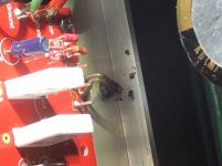
I'm back and still flummoxed. One of my F5T monoblocks blew in late August and I've been chasing the problem ever since. I replaced all of the active components (the MOSFETs and MUR3020 diodes on the output boards and the jfets and cascode transistors on the front end board), upgraded the wattage on many of the resistors, added 470 pF caps across R7 and R10 on the front end boards, and replaced the Keratherm Red insulators with AI203 insulators and thermal paste. This afternoon I dialed down P1 and P2 to 0R, reassembled the amp, plugged the amp into a dim bulb tester, checked the guidance everyone has provided so far and triple-checked everything before turning it on. The bulb lit and slowly dimmed. I breathed a sigh of relief. Then the thermistor on the P side flared and burnt out (rather impressively).
The photo shows the thermistor after I pulled it away from its point of contact with Q3.
I'm lost.
I don't want an anchor. I want this amp to work. Any suggestions?
Thank you,
Scott
Attachments
AudioSan:
That's possible. The legs of the thermistor are covered in heat shrink but its plausible that there was a gap between the heat shrink and the head of the thermistor. A large hole was drilled into the heat spreader that pins all four MOSFETs on that side to the heatsink; the thermistor pokes through the hole and touches the plastic body of the MOSFET. I thought the thermistor was centered in the hole, but who knows?
Do I need to remove and test all of the active parts (again!) or, if your suspicion is correct, can I get away with just replacing the thermistor?
Regards,
Scott
- Home
- Amplifiers
- Pass Labs
- F5 Turbo Builders Thread