you can skip that XYZ thingie
You are the one who told be to be careful and pay attention so I don't lite myself up. Please tell me why I dont need it so I can be smarter..
JP
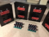
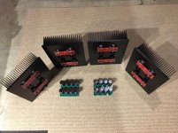
Progress, heat sinks drilled, taped and anodized in black. Amp boards with MOSFETS and diodes installed and soldered.
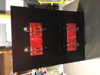
I made L brackets to attach the front panel to the heat sinks.
Now for the front and back panels along with top and bottom panels, more drilling and taping.
I made L brackets to attach the front panel to the heat sinks.
Now for the front and back panels along with top and bottom panels, more drilling and taping.
Attachments
Hi guys,
been running my F5t v2 for about 1,5 years now without any issues...
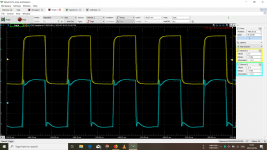
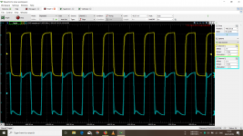
Recently, I bought a Analog Discovery 2 USB scope in order to adjust 2nd harmonics over P3 and so by change started to make different measurements.
My right channel clearly has a big problem... as you can see, the square wave responce is pretty messed up and I have no clue what is the problem here... Sinus looks normal (except the left and right channels have slightly different output voltages). Is it caused by parasitic oscillations?
Please help!
Daniel
been running my F5t v2 for about 1,5 years now without any issues...
Recently, I bought a Analog Discovery 2 USB scope in order to adjust 2nd harmonics over P3 and so by change started to make different measurements.
My right channel clearly has a big problem... as you can see, the square wave responce is pretty messed up and I have no clue what is the problem here... Sinus looks normal (except the left and right channels have slightly different output voltages). Is it caused by parasitic oscillations?
Please help!
Daniel
Attachments
Double check the value of resistors and caps in the circuit. It’s odd that one channel is fine and the other not. Seems like there could be a component value that is off. Verify that there are no big differences between the 2 channels in the connections to the ps, chassis ground, input and output connections.
Checked all the values and they are all correct. I had bought the output mosfets matched off ebay. Could it be that its due to unmatched components?
That is easy to check as far as dc balance goes. When the amp is warmed up check the voltage across the source resistors for each mosfet pair. They should be reasonably close.
What about your input stage jfets. What are you using and are both channels from the same supplier?
If you measure the frequency response on the misbehaving channel can you see a rise in frequency response at high frequencies? Is the 1khz gain the same for both channels?
Have you verified that you have solid connections to the amp’s outside world, -power supply, input, output, chassis ground and that those connections are configured the same as the good channel?
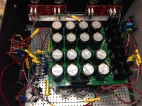
Progress, heat sinks drilled, taped and anodized in black. Amp boards with MOSFETS and diodes installed and soldered.
I made L brackets to attach the front panel to the heat sinks.
Now for the front and back panels along with top and bottom panels, more drilling and taping.
elwood625:
I suggest you leave room in your enclosures for a third capacitor stage (i.e., a CRCRC power supply). I built a pair of F5T V3 monoblocks with a CRC power supply in each chassis (160,000 uF per chassis) and, after living with the amps for about 2 years, added another 90,000 uF to each amp. I'm glad I did.
Regards,
Scott
Attachments
Dc offset and bias are adjusted... 260mV at 34V PSU voltage. Offset is 0. Jfets are from diyaudiostore, so should be fine. I will try to remeasure again today
Could this be due to a cold solder joint raising the resistance of a component on the FE board?
Have you measured that the cascodes are working properly? The FE boards can be run without hooking up the outputs.
Do you measure the same bias with shorting plugs as you do when nothing is connected?
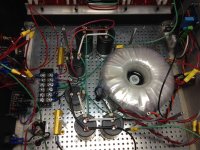
My dc offset jumps up whith open inputs. Bias not checked yet. Hadn't had much time today, will try to check again tomorrow. This could be also not optimal cable routing, the cables (V+, V-) and ground for right channel are running from the left side and are longer... Will post some photos tomorrow
SRMcGee -
How did the added caps improve the amp?
elwood625:
You could probably achieve a similar effect by playing with P3, but the additional capacitance bolstered the low end of my monoblocks without adversely affecting the speed or dynamics of the amplifier. Too little capacitance in the power supply of a Class A amp results in audio anemia; music lacks weight, the bass is deficient and the presentation is thin. Too much capacitance in the power supply of a Class A amp results in a sluggish, dense sound. When I built the F5T V3, I was able to participate in a group buy that Buzzforb hosted, and he supplied 10,000 uF 50v Nichicon KG caps for the power supply. Sixteen of those caps per chassis takes up a fair amount of space, but I used the Deluxe 5U enclosures. The third stage I later added consisted of six 15,000 uF Nichicon KG caps per chassis (and a pair of 0.1R 50W power resistors). I have no idea what the ideal capacitance of the F5T V3 is (yes, I know that NP proposed 160,000 uF in his white paper) and doubt I've hit the mark, but am confident that your amp would respond well to a beefier power supply.
As a point of comparison, the amplifiers in my main system before the F5T were one of the last pairs of Aleph 1.2 monoblocks produced by Pass Labs, and I believe those amps boasted 500,000 uF in each chassis' power supply. I loved that Aleph 1.2 amp but like the F5T V3 better -- it's a little leaner and faster, and its presentation (i.e., soundstage) seems a bit more real to me.
I'm not suggesting you add any more capacitance to your power supplies now. I am suggesting that you leave room just in case, after you've had a chance to get used to their sound, you decide it might be fun to tweak things a bit.
By the way, what you've completed so far looks beautiful.
Regards,
Scott
My dc offset jumps up whith open inputs. Bias not checked yet. Hadn't had much time today, will try to check again tomorrow. This could be also not optimal cable routing, the cables (V+, V-) and ground for right channel are running from the left side and are longer... Will post some photos tomorrow
Nelson mentioned that cascodes can oscillate, and suggested a 100 Ohm resistor inline with each jfet drain to control that.
I also have the same issue, but have not yet corrected it -- my amp is still in rewiring mode....
- Home
- Amplifiers
- Pass Labs
- F5 Turbo Builders Thread