Sounds like possible rf oscillation. Running without any input connected is not a normal situation and if there is any tendency to oscillate that is when you will see it. The dc offset you are measuring with open circuit could be the result of rf oscillations which upset the dc operating points and can confuse measuring equipment that is not designed to measure RF.
In my f5ts I used the compensation caps that Nelson recommended and also increse the gate resistors to prevent this from happening.
In my f5ts I used the compensation caps that Nelson recommended and also increse the gate resistors to prevent this from happening.
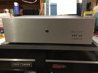
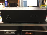
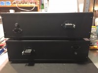
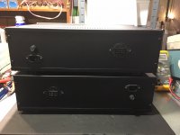
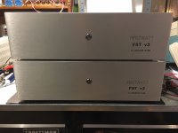
Newly Completed Stereo F5T V2
Hi All,
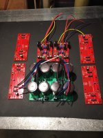
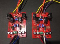
A friend wanted to have a go at DIYing a Pass design that is reasonably powerful and since I have some experience with F5T and MoFo, I agreed to help him with it. After some weighing on cost, speaker load & physical space requirements etc. we arrived at the decision to build a single chasis stereo F5T V2. We considered a few choices of PCB, including the ones from diyAudio Store, but my friend feels that 3 boards per channel would be too complicated for him, so we looked for a single board per channel version, and found a version made by fellow diyaudio member La Mer who has posted about his boards previously on the forum, which got the permission of Papa to make the boards(he forwarded a copy of the e-mail to me).
His board is slightly altered from the original V2 circuit, in which there are 2 pairs of fast recovery diodes in parallel with the source resistors with 2 pairs of output transistors in the article, while La Mer has changed it to 1 pair of diodes for 2 pairs of output transistors, and he has also used a different fast recovery diode (S10A2CIC by KEC) instead of MUR3020W as in the original design to save space (it is a TO220 package).
Anyway, long story short, it is completed and biased up (after changing R5 & R6 from 1k to 2 x 4.7k in parallel). Voltage across the 1 ohm source resistors come up to 290mV, with the output offset around 15-20mV. I attach some pictures taken while it is breaking in and playing some music paired with B1 buffer.


My friend is a new to DIY world, and is very impressed with the sound of the F5T. on behalf of my friend, I would like to express our gratitude to Papa Pass for sharing the wonderful design. Thanks a million!
Best regards
Liu
Hi All,
A friend wanted to have a go at DIYing a Pass design that is reasonably powerful and since I have some experience with F5T and MoFo, I agreed to help him with it. After some weighing on cost, speaker load & physical space requirements etc. we arrived at the decision to build a single chasis stereo F5T V2. We considered a few choices of PCB, including the ones from diyAudio Store, but my friend feels that 3 boards per channel would be too complicated for him, so we looked for a single board per channel version, and found a version made by fellow diyaudio member La Mer who has posted about his boards previously on the forum, which got the permission of Papa to make the boards(he forwarded a copy of the e-mail to me).
His board is slightly altered from the original V2 circuit, in which there are 2 pairs of fast recovery diodes in parallel with the source resistors with 2 pairs of output transistors in the article, while La Mer has changed it to 1 pair of diodes for 2 pairs of output transistors, and he has also used a different fast recovery diode (S10A2CIC by KEC) instead of MUR3020W as in the original design to save space (it is a TO220 package).
Anyway, long story short, it is completed and biased up (after changing R5 & R6 from 1k to 2 x 4.7k in parallel). Voltage across the 1 ohm source resistors come up to 290mV, with the output offset around 15-20mV. I attach some pictures taken while it is breaking in and playing some music paired with B1 buffer.
My friend is a new to DIY world, and is very impressed with the sound of the F5T. on behalf of my friend, I would like to express our gratitude to Papa Pass for sharing the wonderful design. Thanks a million!
Best regards
Liu
Liu, that is a really nice and clean build. Congratulations and Kudos for helping get someone else into the DIY world. I bet it sounds great, very nice work.
gabo
Thanks gabo. I think the sound of the F5T got my friend hooked, and he is considering to start a preamp project e.g. B1 or B1 Nutube soon.

B1 and NuTube B1 are polar opposites in terms of sound.
This friend of mine owns a Line Magnetic 508IA tube amp, so I think he might like the NuTube B1 more. He likes the combination of my B1 and his F5T as it is now though.
The NuTube goes very well with the F5T, I have the same combi!Thanks gabo. I think the sound of the F5T got my friend hooked, and he is considering to start a preamp project e.g. B1 or B1 Nutube soon.
matchedd outputs is a must
regarding input , it should be irrelevant is there dead short or 1K or whatnot, when everything is ok
Thanks!
Sounds like possible rf oscillation. Running without any input connected is not a normal situation and if there is any tendency to oscillate that is when you will see it. The dc offset you are measuring with open circuit could be the result of rf oscillations which upset the dc operating points and can confuse measuring equipment that is not designed to measure RF.
In my f5ts I used the compensation caps that Nelson recommended and also increse the gate resistors to prevent this from happening.
The compensation caps are in place.
My scope does not show any oscillation..... it shows noise in the 20-500 MHz range around 1mV when referencing case as ground....well above the bandwidth of the amp.
I'm going revisit this amp once I get a proper set of outputs installed.
Bfpca,
In the event that my scope is mis-reading the frequencies it reports (entry level Rigol), When taking the outputs off, I noticed that the anti-oscillation caps were not properly soldered to the boards on the bad channel.
It is better to be soldered directly to traces, which is top side. They were soldered on the rear strain relief pads with minimal solder only. There was enough room to get to the top side legs/pads and make the connection directly to the fat traces.
The other option would have been to mount them from the back an solder normally, to get good heat to those big fat traces.
All resistors were re-flowed as well.
Thanks.
BigE
Try putting a capacitor across the input, say 1uf film cap. This should shunt any RF input to ground while leaving any DC unaffected. Do this with the amp off and then power up. See if you still have an offset problem.
Hi Bfpca,
There is 1,5nF mica cap from RCA shield screwed directly to case on both channels. input shields are not bonded as this is dual mono.
I took it apart now, to prepare for new matched outputs.
You have a PM.
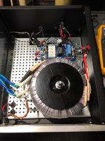
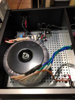
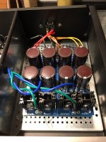
Finally finished my separate power supplies for my F5T v3 balanced amps. I have 49.8vdc +- on one and 50.2vdc +- on the other. Soft start with 800va transformers, 8 10,000uF caps with the seven 0.47ohm resistors for the CRC filter and 8 Vishay MUR3020 diodes. The switch is illuminated by the 18v secondaries on the transformers, with an LED for the V+ and V- on the diyAUDIO power supply board.
Next are the umbilical cables to connect the power supply to the amps using 8 pin Cinch Jones connectors. 2 pins for V+, 2 pins for V- and 4 pins for ground. I'm going to add an external banana plug chassis ground to connect the power supply chassis to the amplifier chassis.
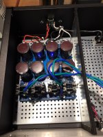
The amplifier section each have an additional 8 10,000uF caps with 4 0.47 ohm resistor for the CRC filter
Next are the umbilical cables to connect the power supply to the amps using 8 pin Cinch Jones connectors. 2 pins for V+, 2 pins for V- and 4 pins for ground. I'm going to add an external banana plug chassis ground to connect the power supply chassis to the amplifier chassis.
The amplifier section each have an additional 8 10,000uF caps with 4 0.47 ohm resistor for the CRC filter
Attachments
Now for #2, I made metal dividers between the AC section and the DC section. I used felt around the edges to prevent any rattles or pops from heat expansion. Then black RTV under the mounting surface of the dividers.
Attachments
Looks good. I think you will really enjoy your amps. I love mine.
I built F5V3 monoblocks with separate power supplies a couple of years ago. I used 800va transformers as well with about 46v supplies. It is a lot of work building up 4 chassis!
I found that my power supplies barely get warm. I am biased at just over 2 amps for about 65watts classA into 8ohms. Heatsinks run at 45-48c.
I went with Jensen input transformers to get balanced or SE inputs. With transformer input I never get hum unless it is in the incoming signal whether it’s se or Bal. No ground issues. Built like this the amps are extremely quiet. Mine are on the bench right now getting speaker protection installed.
The FE boards and amplifier boards with the CRC filter, have an internal measurement of 220mm wide X 320mm long for an enclosure. I'm hoping to find heat sinks so I can stack the heat sinks vertical so the enclosure has a small foot print and is tall.
The cascode transistors and Caddock resistors have heat sinks on them. I lifted the heat sinks about 3mm above the pc board surface and used hot glue to stabilize the heat sinks so not to stress the leads.
I used paint dots to mark the pots for which way to turn the adjusting screw to increase, when the time comes to adjust bias, it will be one less thing for my little mind to remember.
Where can I find heat sinks and what size should they be?
Attachments
TJ - I had Q7 positioned that way originally, then when I was checking the boards for a second time, I convinced myself they were in backwards. Thanks for the heads up, I hate desoldering as I suck at it.
I'm using 2SC4793 for Q7 and 2SA1837 for Q8. I bought the transistor kit from the diyaudio store.
I'm using 2SC4793 for Q7 and 2SA1837 for Q8. I bought the transistor kit from the diyaudio store.
- Home
- Amplifiers
- Pass Labs
- F5 Turbo Builders Thread