Yes, shaving both sides.
I started by dismantling a few damaged ones. and then tested a couple of new ones.
I would forget which is P and N and have a mess.
This seems a long way to go. Was't there a thread about a little heatsink that coupled 2 TO92 devises? Here is one: http://www.diyaudio.com/forums/solid-state/135154-next-best-thing-2sk389-2sj109.html#post1690438
Rush
After my successful (sort of) attempt at the F5 a couple of years ago, I decided to get my feet wet with a full-fledged build including a nice chassis. I chose cViller's F5c schematic, added P3 and implemented the newer connection of TH1/2. Or you could say I picked the F5 Turbo V1, and added current limiting and a cascode. I needed a lot of swing but not much current capability as my load is a very gentle 8 ohms, but low sensitivity.
The build is essentially a balanced amplifier, with one F5T 'Module' per signal half. I understand that matching of halves is going to be a task in itself. One major schematic change I was hoping to make was to connect the wiper of P3 to ground instead of Pin1 to help with adjusting the circuit symmetry. The other big change was using much less feedback, which in my case stands at about 30dB total - 24dB per 'Module' and 6dB from balanced operation. This is about twice the F5T schematics. If it doesn't work out well I will double up the feedback resistors and look for more voltage upstream.
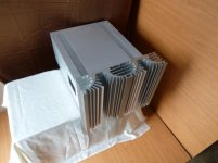
The power supplies will be 8x10000uF and 8x22000uF per monoblock, with 8 0.22 ohm resistors, all running off a 25V, 1KVA transformer and dual MUR3060 bridge rectifiers. This will give me a total of above 0.5F on 32V rails across both channels, hopefully that will be enough or just about. The heatsink and case are pictured here - 12" high at the sinks, 20" deep. The narrow width means copper heatspreaders are absolutely required (also because the sink has a vertical contact patch). I have all the components I need, just waiting for PCBs to be designed and printed. Career situation permitting, I should have more progress in a few months.
The build is essentially a balanced amplifier, with one F5T 'Module' per signal half. I understand that matching of halves is going to be a task in itself. One major schematic change I was hoping to make was to connect the wiper of P3 to ground instead of Pin1 to help with adjusting the circuit symmetry. The other big change was using much less feedback, which in my case stands at about 30dB total - 24dB per 'Module' and 6dB from balanced operation. This is about twice the F5T schematics. If it doesn't work out well I will double up the feedback resistors and look for more voltage upstream.
The power supplies will be 8x10000uF and 8x22000uF per monoblock, with 8 0.22 ohm resistors, all running off a 25V, 1KVA transformer and dual MUR3060 bridge rectifiers. This will give me a total of above 0.5F on 32V rails across both channels, hopefully that will be enough or just about. The heatsink and case are pictured here - 12" high at the sinks, 20" deep. The narrow width means copper heatspreaders are absolutely required (also because the sink has a vertical contact patch). I have all the components I need, just waiting for PCBs to be designed and printed. Career situation permitting, I should have more progress in a few months.
Attachments


Yes,
I was thinking of getting a post and packing quote from that Indian manufacturer.
http://www.perfectmetal.in/contactus.html
Could it become a UK Group Buy?
I was thinking of getting a post and packing quote from that Indian manufacturer.
http://www.perfectmetal.in/contactus.html
Could it become a UK Group Buy?
Almost every Indian aluminum manufacturer has this profile in their catalog, minimum order is one bar - 6 feet, and cost is about INR 3000/- per foot for raw unfinished sinks, IIRC. That would be about $55 today and is a good time because dollar is quite high against Indian Rupee (bad for us who have to import everything). However I suspect you might get better/cheaper sinks from European suppliers.
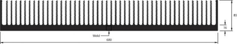
In the site AndrewT has linked, this is N34 profile, on page 7 of the catalog. I outsourced the entire job to an outfit called Soundfoundations that does this sort of work (woulda posted the link but it might be advertising). The sinks were bought from Jindal, another, older/more established company. I've used the same profile in slightly shorter (10") length for my earlier F5 attempt and it was really good, the sink temperatures never crossed 60 degrees in the hot summer - each sink was dissipating 75 watts as my bias was a touch more than default. My room was a different matter though, so the F5 remains a winter-only amplifier")
This build will see about 300W dissipation per monoblock, I'm hoping the sinks will manage or I will have to back it down to about 200W or so.
In the site AndrewT has linked, this is N34 profile, on page 7 of the catalog. I outsourced the entire job to an outfit called Soundfoundations that does this sort of work (woulda posted the link but it might be advertising). The sinks were bought from Jindal, another, older/more established company. I've used the same profile in slightly shorter (10") length for my earlier F5 attempt and it was really good, the sink temperatures never crossed 60 degrees in the hot summer - each sink was dissipating 75 watts as my bias was a touch more than default. My room was a different matter though, so the F5 remains a winter-only amplifier
This build will see about 300W dissipation per monoblock, I'm hoping the sinks will manage or I will have to back it down to about 200W or so.
I got quotes from perfect metal a couple of weeks back.They approximately $ costs for 1 feet segments
N1- 30$
N34- 27$ (PDF catalog says 30kg/m, website correct it to 16kg/m)
N56-60$
Taxes+shipping extra.
They are dealers & not producers so these would perhaps be Hindalco profiles
N1- 30$
N34- 27$ (PDF catalog says 30kg/m, website correct it to 16kg/m)
N56-60$
Taxes+shipping extra.
They are dealers & not producers so these would perhaps be Hindalco profiles
Last edited:
apologies if this has been definitively addressed elsewhere, but is it safe to say that the 5U chassis now in the DIYAudio store is probably not up to a fully-biased 32V-rail Turbo V1? i see the rating of 0.28C/W reference in the chassis webpage and assumed this was probably for one side/set of 2 sinks, but didn't know for sure (i don't have a real good handle on heat dissipation figures yet).
while there's a lot more to it than heatsink surface area, obviously, a rough calculation shows that, not counting the waviness, these sinks are only about 10% larger in radiating area than a set of the 10" profiles from HeatsinkUSA that are 6" tall (what i used in my basic 25Wpc F5, borderline for that as-is). i don't know if there's enough magic in the chassis/profile to make up the difference.
while there's a lot more to it than heatsink surface area, obviously, a rough calculation shows that, not counting the waviness, these sinks are only about 10% larger in radiating area than a set of the 10" profiles from HeatsinkUSA that are 6" tall (what i used in my basic 25Wpc F5, borderline for that as-is). i don't know if there's enough magic in the chassis/profile to make up the difference.
its 0.28C/W pr SINK. so 0.14C/W pr side. they can handle a 2ch V2 fine.apologies if this has been definitively addressed elsewhere, but is it safe to say that the 5U chassis now in the DIYAudio store is probably not up to a fully-biased 32V-rail Turbo V1? i see the rating of 0.28C/W reference in the chassis webpage and assumed this was probably for one side/set of 2 sinks, but didn't know for sure (i don't have a real good handle on heat dissipation figures yet).
while there's a lot more to it than heatsink surface area, obviously, a rough calculation shows that, not counting the waviness, these sinks are only about 10% larger in radiating area than a set of the 10" profiles from HeatsinkUSA that are 6" tall (what i used in my basic 25Wpc F5, borderline for that as-is). i don't know if there's enough magic in the chassis/profile to make up the difference.
Last edited:
its 0.28C/W pr SINK. so 0.14C/W pr side. they can handle a 2ch V2 fine.
thanks, i always appreciate your insight AudioSan. looking again at the numbers, i think you must be right about what is what.
but if you don't mind, i'd like some help understanding why a single 165mm(H)X 300mm(D) sink is roughly 10% worse at dissipating heat than a single 200mm*200mm. the former has roughly 20% more surface area, and i read elsewhere on this thread or another that a lower, wider sink is more efficient than a taller, narrower one. is a "square" actually the optimal profile here?
Taller sinks have warm air wafting over the fins. That reduces the effectiveness of the upper parts of the fins.
A very rough calculation (model/simulation) based on using sqrt(height) gives some idea of what to expect.
Take a 50mm high 200mm wide sink. Let's say it has Rth s-a = 1C/W
Double it to 100mm high and the Rth s-a is likely to be around 0.7C/W (sqrt[50/100]=0.7)
Double again to 200mm high and Rth s-a is likely to be around 0.5C/W (sqrt[50/200]=0.5)
Double again to 400mm high and Rth s-a is likely to be around 0.35C/W
Very short and very tall heatsinks move further away from the sqrt rule.
Now instead double the width. All the fins in the 200mm wide version are running at the same temperatures as the 400mm wide version.
Remember, when Rth s-a is measured and specified, it is for the back plate at isothermal temperature. This means the interface surface of the whole backplate is at the same temperature (Ts). This means there are no cooler spots/areas to reduce effectiveness of the fins.
We need to modify the model to take account of delta T (Ts-Ta). The difference in temperature between A air (Ta) and S backplate (Ts). The sink manufacturers usually give direction in how to derive the delta T de-rating Factor. For delta T ~30C degrees expect DF in the range 1.3 to 1.4
The next correction is for non isothermal operation. I have not seen any manufacturer giving data on this correction.
Some independent software does allow investigation of this. I adopt a much simpler method. Make the extremities out at the corners of the heatsink be at a radius] of less than 10 times the thickness of the backplate. This gets the backplate surface to near the same temperature as the hot spot under the heating device. Copper heatsink can probably manage with a bigger ratio, maybe 12 to 15 times thickness.
This rule would require the 400mm wide heatsink to have a thicker backplate than the 200mm wide heatsink if one expects the modeling to predict operational temperatures.
BTW,
this radius to thickness also applies to the fins. Short fins are effective even though they can be relatively thin. Long fins must be thicker to be as effective. Just apply the 10:1 ratio for fin depth:thickness. This also explains why fins are often tapered and yet not lose much in the way of dissipation effectiveness.
Last edited:
If I understand "rilled" then it depends on how the fins have been shaped.
If the fins "look" line they have been bent into their new shape then basically we have a longer fin of the same thickness. Yes that increases surface area but it also increases it's length:thickness ratio. It still needs to be able to conduct heat right out to the tip.
But there is another way to ripple the surface of the fin. This is to make one side wavy (or zig-zagged) and to make the other side wavy but out of phase this inserts narrowing of the fin without increasing the length. So it keeps the length the same and the surface area increases but the length:thickness ratio goes up if the necked thickness is used as reference.
I believe the first (in phase wavy) method is better then the necked version.
I think you exaggerate using the descriptor "much".
How much does the area actually increase for examples you have seen?
Guys I need an opinion, I have been planing to build an f5t v 2 as I always tought I could use the extra steroids!
Now I've been thinking a bit better and I believe an higher bias f5 should do the trick.
I have a pair of rega rs3 which are 6ohm speakers with aprox 89db sensitivity. and would like to have at least 35-40W in class A and then some headroom in AB.
Acording to the f5 manual at 1.3A bias per device the math is:
2.6*2.6*8=54W and half of that is class A so around 27W
so for a 6ohm speaker to get to the 35-40W target I would have to bias each device between 1.7 and 2 amps using the same voltage. Correct? here come some questions:
Providing adequate heatsinking (I'm thinking 0.2W/C per channel, using a 300x210x40 heatsink) the trasistors should support this right?
Increasing the supply voltage means I would be able to bias the devices at a lower current and still get the same power in class A right?
Now, if I go the turbo route, I would have 2 devices per side and would only bias each at 0.9 or 1A to get to the desired power, and wouldn't need to increase the supply voltage right? Or should I increase the voltage and use lower bias?
So is it better to have 2 devices per side biased at a higher A or 4 devices at a lower bias?
thats what i did too. 1.7A bias to drive 6ohm. however. if you like it to run at higher power then 35W at 6ohm in class A/B. then you also need higher rail voltage.Guys I need an opinion, I have been planing to build an f5t v 2 as I always tought I could use the extra steroids!
Now I've been thinking a bit better and I believe an higher bias f5 should do the trick.
I have a pair of rega rs3 which are 6ohm speakers with aprox 89db sensitivity. and would like to have at least 35-40W in class A and then some headroom in AB.
Acording to the f5 manual at 1.3A bias per device the math is:
2.6*2.6*8=54W and half of that is class A so around 27W
so for a 6ohm speaker to get to the 35-40W target I would have to bias each device between 1.7 and 2 amps using the same voltage. Correct? here come some questions:
Providing adequate heatsinking (I'm thinking 0.2W/C per channel, using a 300x210x40 heatsink) the trasistors should support this right?
Increasing the supply voltage means I would be able to bias the devices at a lower current and still get the same power in class A right?
Now, if I go the turbo route, I would have 2 devices per side and would only bias each at 0.9 or 1A to get to the desired power, and wouldn't need to increase the supply voltage right? Or should I increase the voltage and use lower bias?
So is it better to have 2 devices per side biased at a higher A or 4 devices at a lower bias?
if you want som A/B headroom, then twice the class A power is a minimum. under that is little to no point. that meens +/-32V anyways. so you realy want a turbo
V1 or V2.I like the overall sound of the Turbo in any format better than the original, regardless # of outputs. I've tried them all. More laid back and grunty.
My setup uses 4 of outputs each side biased lower @ ~30v.
This way I keep less wattage on each hotspot and just crank the bias until your heatsinks max out, or get reaches 65c, which ever occurs first. I pretend it's a XP-30A
It probably goes to class B quicker this way, but ah well. Compromises.
My setup uses 4 of outputs each side biased lower @ ~30v.
This way I keep less wattage on each hotspot and just crank the bias until your heatsinks max out, or get reaches 65c, which ever occurs first. I pretend it's a XP-30A
It probably goes to class B quicker this way, but ah well. Compromises.
35W into 6r0 requires ~20.5Vpk and 3.4Apk.
Bias set to slightly more than 1.7A satisfies the ClassA requirement for the 3.4Apk.
Supply that holds up to better than ~25Vdc satisfies the 20.5Vpk.
If you want more ClassA output then increase the bias current.
If you want more power then increase the supply voltage.
All that was posted in #496 para1 to para3 is correct.
I have a feeling that para 4 onward indicate you don't really understand power.
Stick to voltages and currents and don't confuse the understanding by including power.
Regarding transformer choice, NP says in the f5t article that va rating should be at least twice the dissipation of the amp.
With 4 devices per channel and 1A bias at 32v I et 32x8=256w dissipation, so I should go with a trafo with 512va plus extra headroom make that 600VA. Is
my math correct?
With 4 devices per channel and 1A bias at 32v I et 32x8=256w dissipation, so I should go with a trafo with 512va plus extra headroom make that 600VA. Is
my math correct?
- Home
- Amplifiers
- Pass Labs
- F5 Turbo Builders Thread