Very nice indeed, I think alot of people including me will get great ideas. Do you find the vents in the top and bottom plate to be adequate enough for air flow. I am working on some aluminum sheet metal for the top and bottom plates. I was just going to have a big open hole with some wire mesh for the top, but yours looks nice.
Thanks guys I wish I had access to a cnc but I did this with my table saw , chop saw
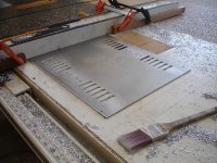
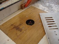
and router. I've a picture from when I cut the tops and bottoms. I wish I had cut the slots longer on my amp as I think it would run cooler. the monos run realy cool plus I prefer the toshibas to the fairchilds not by a wide margen but thay seem a little clearer to me. I kinda wish I built them for myself I think I am going to build a ba-3 pre next maybe a f-4 or burning amp. I built a grounded grid pre about 7 years ago it sounds good to me but I have nothing to compare it to. After looking at these pictures I just want say if you do this please be careful I were good ear potection so I can still hear plus I can concentrate better with whats going on. I drill a hole first for the router bit.
and router. I've a picture from when I cut the tops and bottoms. I wish I had cut the slots longer on my amp as I think it would run cooler. the monos run realy cool plus I prefer the toshibas to the fairchilds not by a wide margen but thay seem a little clearer to me. I kinda wish I built them for myself I think I am going to build a ba-3 pre next maybe a f-4 or burning amp. I built a grounded grid pre about 7 years ago it sounds good to me but I have nothing to compare it to. After looking at these pictures I just want say if you do this please be careful I were good ear potection so I can still hear plus I can concentrate better with whats going on. I drill a hole first for the router bit.
Attachments
Wow the man him self is impressed, that's awesome.
Could you please tell us what router bit you used, and table saw blade. As I have the tops and bottom plates cut out with a plasma. But its hard to make a jig to cult clean, and to cut out the vents.
Thanks for sharing.
Could you please tell us what router bit you used, and table saw blade. As I have the tops and bottom plates cut out with a plasma. But its hard to make a jig to cult clean, and to cut out the vents.
Thanks for sharing.
Thanks that's really cool. So is your circuit.I can hardly wait to build some of your other ones.I remember from burning amp Mr Pass saying that one thing thing he knows for sure is that DIYers are cheap and I know I am. I'm bummed because the nearby electronic surplus store just closed.They did have a 50% off sale just before they closed but still there gone.Anyway Duder I bought a cheap carbide bit with a tapper on top as it will then cut into the pilot hole that I pre drilled as I lower it down. I am a little reluctant to say this but the saw blade I used to cut most of the aluminum was an old blade as I don't want to take the edge off my nicer saw blades.The blade I chose has very little rake was carbide and has a lot of teeth I lubed it often as aluminum is quit sticky. the blade is not the most important thing having a solid fence that's parallel with the blade is a must.If you got the dough buy an aluminum blade I would like t h and cut slow and sure.
h and cut slow and sure.Still struggling with hum problem, totally disconnected B1 and found the problem is actually with F5 or wiring etc.
Basicly when nothing is connected to the amp all fine, as soon as a device mp3 player or phone is connected hum hum hum
If i ground the input from chassis i get hum
If i ground the input from GND i get hum
if i have nothing connected no hum
Basicly when nothing is connected to the amp all fine, as soon as a device mp3 player or phone is connected hum hum hum
If i ground the input from chassis i get hum
If i ground the input from GND i get hum
if i have nothing connected no hum
Making some progress...
I thought posting some pictures will be nice.
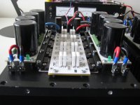
I'm rebuilding my F5Tv2 to a v3.
One channel is done, think I test it first, before buiding the next channel. Curious if it will be stable with the larger output stage.
I'll test it today, hope I don't destroy it
Made some improvements too.
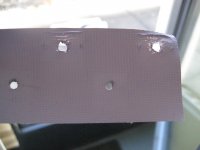
-Used Kerafol 86/82 red for the outputs and diodes. On the first pic you can see it's rather fragile, can't be used twice. I mounted the outputs for a test with M4 bolds with washer, as tight as possible, and it gives too much pressure in the area of the M4 so it destroys the Kerafol.
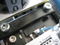
So I decided to make a clamping bar of 4 mm steel just for the outputs. See pictures.
Hope the thermal coupling gets better. Will post the results.
- Coupled the Jfets with some copper and thermal glue.
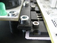
- I glued the new (better) thermistors to the outputs. I have good experience with that, with my standard F5.
- Replaced the 10 Ohm JFet source resistors for Dale CMF55's.
- made the connection to the PSU with faston connectors, so it's easier to disassemble.
- Upgraded the outputs source resistors to 10 Watt with two paralled MPC74 0.47 Ohm resistors. Looks nicer when the whole PCB is filled with components...
- upgraded some cabling with thicker 6mm cable. And for the input no more fragile coax, but twisted signalwire. Like Pa does...
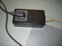
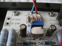
Oh, and I build a DC-filter ( schematic of Rod Elliot) for the mains, see picture, and now all mechanical hum of the big toroids is gone !
I thought posting some pictures will be nice.
I'm rebuilding my F5Tv2 to a v3.
One channel is done, think I test it first, before buiding the next channel. Curious if it will be stable with the larger output stage.
I'll test it today, hope I don't destroy it
Made some improvements too.
-Used Kerafol 86/82 red for the outputs and diodes. On the first pic you can see it's rather fragile, can't be used twice. I mounted the outputs for a test with M4 bolds with washer, as tight as possible, and it gives too much pressure in the area of the M4 so it destroys the Kerafol.
So I decided to make a clamping bar of 4 mm steel just for the outputs. See pictures.
Hope the thermal coupling gets better. Will post the results.
- Coupled the Jfets with some copper and thermal glue.
- I glued the new (better) thermistors to the outputs. I have good experience with that, with my standard F5.
- Replaced the 10 Ohm JFet source resistors for Dale CMF55's.
- made the connection to the PSU with faston connectors, so it's easier to disassemble.
- Upgraded the outputs source resistors to 10 Watt with two paralled MPC74 0.47 Ohm resistors. Looks nicer when the whole PCB is filled with components...
- upgraded some cabling with thicker 6mm cable. And for the input no more fragile coax, but twisted signalwire. Like Pa does...
Oh, and I build a DC-filter ( schematic of Rod Elliot) for the mains, see picture, and now all mechanical hum of the big toroids is gone !
Attachments
-
 PSU connectors.jpg231.8 KB · Views: 284
 -
 DC-filter.jpg329.3 KB · Views: 282
 -
 JFETs coupled with thermal glue and copper.jpg418.3 KB · Views: 305
 -
 better position of NTC.jpg448.2 KB · Views: 460
 -
 Clamp bar.jpg375 KB · Views: 472
 -
 nice.jpg297.6 KB · Views: 502
 -
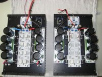 v2 vs v3.jpg406.3 KB · Views: 511
 -
 Kerafol used with to much pressure.jpg184.7 KB · Views: 498
Oh, and I build a DC-filter ( schematic of Rod Elliot) for the mains, see picture, and now all mechanical hum of the big toroids is gone !
Which projectnumber is that?
(I guess I'm a bit tired today, just can't find it...)
Which projectnumber is that?
(I guess I'm a bit tired today, just can't find it...)
Mains DC and Transformers
I used figure 8
Walter
Any hum issues from seperating the boards?
Thanks Buzz!
No, not at all.
You can't really see it on the pics, but I connected the two grounds with 4 x 1,5 mm wires under the PCB. Thought it should be thicker, but like you said earlyer " point of diminishing returns"...
Walter


Check out the single ground point
The earth wire is interlaced with the inputs ground


Learnt a Lesson with the Diyaudio F5T boards, make sure the solder connections are realy good filling both sides of the board, some connections on the PCB are the top side only, I had a problem where I couldn't Bias up the let channel but fixed it now.
anyway Ive sorted out most of the issues now and Ive redone the power supply with thicker solid wire, there is no hum on either channel if only one channel has the Mp3 player connected. as soon as I connect to both channels RCA's I get loads of hum still. I find it rather odd that having only one channels RCA connected and its ok. so still wondering what the hell is going on lol
So I need help to understand how this can happen somehow both channels are interacting in a wierd way.
Last edited:
- Home
- Amplifiers
- Pass Labs
- F5 Turbo Builders Thread