Just a simple question.
In the opinion of those people who have build using both the DIYAudio and TeaBag boards; are the DIYAudio builds more prone to oscillation compared to the TeaBag builds?
If so, could it be because of the longer distances to the outputs?
I am planning a F5T V3 build using TeaBag's boards and the Toshiba 2SK1530/2SJ201 devices (4 pairs), but biased not that high, maybe to just get to 50W. Opinions please.
The reason I plan on using 4 pairs is because the Toshiba's can only handle 12A, and so I guess in my uneducated opinion I thought more devices is better to handle the same load as 2 pairs of IRF or Fairchild devices.
OK, it was not a simple question.
I like your idea of more pairs and less bias. You get more current headroom and have less worries of heat. While your total heat may be the same as a two pair version, it will be spread over more devices and will bring individual Fet temperature down. I did not have an oscillation problem with the store boards, but I think I am one of maybe two or three people who have built it. No issues with Teas boards either. I like how you can spread out the store boards, but do not liking the wiring setup. That being said, I don't think its an issue other than layout. Change Rs to 1R resistors.
Well Have the F5T up and running and heres the good and the bad
good - sounds good!
bad - Transformer not quiet and is humming quite a bit
bad - The chronic hum is appearing on the output of both channels and sounds the same as the transformer hum! un-listenable!!
good - DC offset has been set to almost 00v but still hum
bad - May not be able to bias past 0.1v (to be confirmed)
good - 33v PSU + & -
Damn! and I was realy hoping this would go perfect on the first shot!

Any ideas ?
Ill check if transformer Hums when connected to just the B1
and also iv'e left out the .0033 Capacitor as i figured i wouldn't need it with using a IEC Filter.
Off to bed......... troubleshooting tommorow
good - sounds good!
bad - Transformer not quiet and is humming quite a bit
bad - The chronic hum is appearing on the output of both channels and sounds the same as the transformer hum! un-listenable!!
good - DC offset has been set to almost 00v but still hum
bad - May not be able to bias past 0.1v (to be confirmed)
good - 33v PSU + & -
Damn! and I was realy hoping this would go perfect on the first shot!
Any ideas ?
Ill check if transformer Hums when connected to just the B1
and also iv'e left out the .0033 Capacitor as i figured i wouldn't need it with using a IEC Filter.
Off to bed......... troubleshooting tommorow
Last edited:
First things first. What is Vdrop acros Jfet Rs? If tit is around 6-7mA, them you should be able to bias output fets. If you can't raise voltage high enough, then you may need larger pots. With F5, it is good idea to bias up evenly, as one side can hog from the other some time. If you can bias it up to proper Vdrop across output fets sorce resistors, then check to see of you have decent current sharing If you do, then adjust offset. All should be well. If hum remains, redo PSU boards and make sure transformer is of sufficient VA rating. Try twisting transformer to see if that helps hum.
Use DMM on AC setting to check for oscillation on output, but I suspect your PSU.
Use DMM on AC setting to check for oscillation on output, but I suspect your PSU.
Rixsta
With regards to your hum: I would first sort out the inputs to determine if the hum is caused by a ground loop on the signal circuit or PSU. If the hum disappears when you short the inputs then you must look at how you connected your signal ground. Else it would be PSU and then have a closer look at how you grounded your PSU, wiring routing and all sorts of other problems.
Your trafo; does it have center-tapped or separate secondaries? From the pic it looks like center-tapped, just want to make sure from you.
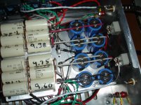
Also, your PSU boards: is it CRC? Because it looks weird since the R is on one side of the caps.
Another thing: your transformer looks a bit on the wee side. What is the VA rating?
With regards to your hum: I would first sort out the inputs to determine if the hum is caused by a ground loop on the signal circuit or PSU. If the hum disappears when you short the inputs then you must look at how you connected your signal ground. Else it would be PSU and then have a closer look at how you grounded your PSU, wiring routing and all sorts of other problems.
Your trafo; does it have center-tapped or separate secondaries? From the pic it looks like center-tapped, just want to make sure from you.
Also, your PSU boards: is it CRC? Because it looks weird since the R is on one side of the caps.
Another thing: your transformer looks a bit on the wee side. What is the VA rating?
Last edited:
I guess I was lucky with my build using Teabags boards which is a cascoded 2 pair version running at +- 36V.The amp runs silently and sounds brilliant;I'm sure its getting better over time.Like Henryve I'm tempted to change to a 4 pair amp with lower bias;maybe later in the year.
I agree with PKI changing components on these thick pcb's would have been a nightmare;I can destroy a normal type board as easy as anything attempting to swap things.It was a huge relief when it worked from the get go.
I agree with PKI changing components on these thick pcb's would have been a nightmare;I can destroy a normal type board as easy as anything attempting to swap things.It was a huge relief when it worked from the get go.
I never knew touching the thermistor would give me a quick 240v zap! nothing tells you in big bold letters don't touch thermistors and wrap them in heat shrink lol, oh well still alive lol. Will reply to each of your replys one by one
buzzforb, I don't know how to measure as you say so have done voltage, Jfet as follows
first fet
D is 29v
G is 11.4mv
S is 60mv
oposite fet
D is 29v
G is 11.3
S is 60mv
Output DC is 10mv
I have the bias very low 0.06v on Both channels just for testing, DC still hum even tho those numbers are fairly equal.
Transformer is 600va centre-tapped I was told and has mechanical Hum altho not that bad lol,
Thanks
Last edited:
henryve,
Problem Half solved! Disconnected right input channel from the B1 and hum on BOTH channels stopped, so im guessing there is a problem with the B1. last time I had disconnected only the left channel from B1 and hum remained. so as we see that B1 may not be right, ill post in the B1 thread ;-)
I had noticed that B1 that music going in was quieter than what came out, so i think I need to troubleshoot that board, everything seems ok when F5t is disconnected from B1!
Last edited:
Rixsta
Also, your PSU boards: is it CRC? Because it looks weird since the R is on one side of the caps.
Its the same as in F5t schematic just a bit wierd looking how i fit it in, one board is the positive one the negative. ac input -> diodes -> 5 caps down one side then the resistors then 5 more caps then output.
Its the same as in F5t schematic just a bit wierd looking how i fit it in, one board is the positive one the negative. ac input -> diodes -> 5 caps down one side then the resistors then 5 more caps then output.
Ah, OK. Make sense now.
Measure across 10R resistors on the source pin of the Jfets. That tells you your current on the FE. Same as when you measure across output fets source resistors. You should bias with both inputs grounded. If all looks good on bias and offset, check for AC oscillation. If that is clear, hook up speakers. If you have no hum, then your amp is good and your build is quiet. If you hook up a pre and you get hum, you either have a pre issue or a ground loop is being created by the hookup. It looks as though you have found the problem though.
There is only one thing about Teas boards: they are not friendly for constant changes. The board it too thick and a nightmare to desolder parts (at least for me). If you need build and forget about amps, they are perfect!
I haven't used TeaBag's F5T boards, but you need a rework station for any board with pads on both sides for three legged (or more) desoldering.
MCM has one for only $49.
Tenma Hot Air Rework Station | 21-11425 (2111425) | Tenma
I used one like it to remove multi-turn pots on TeaBags F6 boards where I put in the wrong value and removed and saved the pots for future use. I think it is OK for MOSFET removal, no static like a vacuum desolderer.
Rush
Thanks for the link I didn't even know these existed, have you had any luck using it with point to point wiring.I haven't used TeaBag's F5T boards, but you need a rework station for any board with pads on both sides for three legged (or more) desoldering.
MCM has one for only $49.
Tenma Hot Air Rework Station | 21-11425 (2111425) | Tenma
I used one like it to remove multi-turn pots on TeaBags F6 boards where I put in the wrong value and removed and saved the pots for future use. I think it is OK for MOSFET removal, no static like a vacuum desolderer.
Rush
I haven't used TeaBag's F5T boards, but you need a rework station for any board with pads on both sides for three legged (or more) desoldering.
MCM has one for only $49.
Tenma Hot Air Rework Station | 21-11425 (2111425) | Tenma
I used one like it to remove multi-turn pots on TeaBags F6 boards where I put in the wrong value and removed and saved the pots for future use. I think it is OK for MOSFET removal, no static like a vacuum desolderer.
Rush
Desoldering is greatly simplified if the thru-holes are made larger than the "default" sizes provided by most PCB design packages. It there are components that are likely to need frequent desoldering, such as the output MOSFETs or the source resistors, you might even consider using Molex connectors.
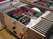
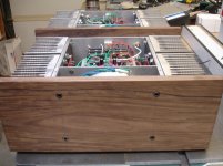
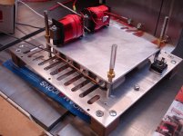
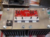
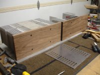
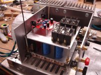
Last week I completed the F5T project that I have been working for a good friend.
After he heard my F5T he wanted one so I built him one. He wanted mono amps.
what a pain he is sometimes but as it worked out these turned out quit well as they are dead quiet. These are have Toshiba outputs biased at .6 mv over a 1/2 ohm Resistor. and run quit cool. I ran a wire from the lower caps before the inductors to the main ground and grounded the remaining caps at the same point along with all other grounds. I also reworked my amp (fairchild outputs) to a mono configuration and star ground here are some pix. I put the store boards upside down as this put the mosfets in a more appropriate place.My amp is now dead quiet too.
Attachments
- Home
- Amplifiers
- Pass Labs
- F5 Turbo Builders Thread