Hi everyone!
I'm really excited to get started on building an F5. i've heard nothing but great things about the amp, so I bought some boards from the DiyAudio store, and here we go.
P-F5-2V20 - Pair of F-5 boards (Makes 2 channels; Rev 2.0) - Boards
Anyways, the boards are V2.0 dated 2010-10-23 caviler layout
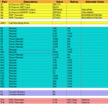
So I have the BOM
Attached is the BOM, and I have several questions. I plan on just throwing all the board components into a Mouser project, and ordering. They don't seem to have all the transistors, and I will discuss them later.
Just one questions for resistors... well two actually. I know K means 1000, so 100K=100,000
But what does R mean? Like 10R, 100R, 0.47R 150R, etc?
Also, I'm going to use metal film resistors? Is that okay?
As for the pots, P1, and P2 are both 5K. Can someone point me to the mouser part number (or digikey) for the pot? I can find a lot of 5K pots, but I need one that fits in the holes. One with the right spacing.")
As for the NTC thermistor, its 4.7K.. whats the wattage? Can someone point me a link or something?
Also, what about LED1? What should I use for that? Again, a link would help me.
Now onto transistors.
Q1: 2SK170
Q2 2SJ74
Aren't these transistors difficult to find? I heard one of them was discontinued with no replacement.. I have a source for them, but do they need to be matched? If they do, what is it for? Low DC offset?
As for Q3 and Q4, what website has them?
What brand should be used for them? Any matching needed for these? I know they are the outputs.
As for Q5 and Q6, Mouser has them.. nuff said. But do they need to be matched?
Now with all that done, heres the other set of questions.
___________________________________________________________________
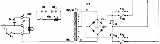
Transformer should be a 18-0-18. What VA would work? Can I simply wire up the power supply like in a Hafler DH-200?
I would simplify if though. I would get rid of the thermal breakers, as they would be on the PCB, and get rid of the high temp lamp.
The center tap of the transformer is connected to the ground bus between the two filter capacitors. For filter caps, would two 22,000µF work? Also, having an B+ and B- fuse for each channel. Thats my plan for the wiring. The ground of the RCA jacks is grounded to the bus bar, and so is the negative output for the speakers. Fuses will be put inline with the positive speaker output.
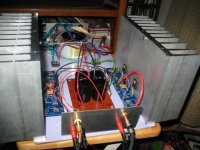
As for a chassis, I'm simply reusing an old Yamaha receiver.. Don't worry, the heatsinks are huge.
___________________________________________________________________
Sorry for some of the stupid questions, but I'm not an electronics genius yet. I'm only 16, and money is an issue, so thats why I'm not going to buy fancy resistors and stuff. Just regular components.
Thanks so much for the help!
-Nick
I'm really excited to get started on building an F5. i've heard nothing but great things about the amp, so I bought some boards from the DiyAudio store, and here we go.
P-F5-2V20 - Pair of F-5 boards (Makes 2 channels; Rev 2.0) - Boards
Anyways, the boards are V2.0 dated 2010-10-23 caviler layout
So I have the BOM
Attached is the BOM, and I have several questions. I plan on just throwing all the board components into a Mouser project, and ordering. They don't seem to have all the transistors, and I will discuss them later.
Just one questions for resistors... well two actually. I know K means 1000, so 100K=100,000
But what does R mean? Like 10R, 100R, 0.47R 150R, etc?
Also, I'm going to use metal film resistors? Is that okay?
As for the pots, P1, and P2 are both 5K. Can someone point me to the mouser part number (or digikey) for the pot? I can find a lot of 5K pots, but I need one that fits in the holes. One with the right spacing.
As for the NTC thermistor, its 4.7K.. whats the wattage? Can someone point me a link or something?
Also, what about LED1? What should I use for that? Again, a link would help me.
Now onto transistors.
Q1: 2SK170
Q2 2SJ74
Aren't these transistors difficult to find? I heard one of them was discontinued with no replacement.. I have a source for them, but do they need to be matched? If they do, what is it for? Low DC offset?
As for Q3 and Q4, what website has them?
What brand should be used for them? Any matching needed for these? I know they are the outputs.
As for Q5 and Q6, Mouser has them.. nuff said. But do they need to be matched?
Now with all that done, heres the other set of questions.
___________________________________________________________________
Transformer should be a 18-0-18. What VA would work? Can I simply wire up the power supply like in a Hafler DH-200?
I would simplify if though. I would get rid of the thermal breakers, as they would be on the PCB, and get rid of the high temp lamp.
The center tap of the transformer is connected to the ground bus between the two filter capacitors. For filter caps, would two 22,000µF work? Also, having an B+ and B- fuse for each channel. Thats my plan for the wiring. The ground of the RCA jacks is grounded to the bus bar, and so is the negative output for the speakers. Fuses will be put inline with the positive speaker output.
As for a chassis, I'm simply reusing an old Yamaha receiver.. Don't worry, the heatsinks are huge.
___________________________________________________________________
Sorry for some of the stupid questions, but I'm not an electronics genius yet. I'm only 16, and money is an issue, so thats why I'm not going to buy fancy resistors and stuff. Just regular components.
Thanks so much for the help!
-Nick
Attachments
I may do that, but it may be cheaper just to buy the components on my own.
Is a 400VA transformer enough to drive two channels?
Antek - AS-4218
Is a 400VA transformer enough to drive two channels?
Antek - AS-4218
and if you need heatsinks , these are more than adequate 10.080" Wide x 7" Long Heatsink - HeatsinkUSA, LLC Store
Have also a look at cviller's blog entry on the subject:
http://www.diyaudio.com/forums/blogs/cviller/191-gb-f5-guide-pcb-version-2.html
http://www.diyaudio.com/forums/blogs/cviller/191-gb-f5-guide-pcb-version-2.html
Hi ouimetnick,
I just got my F5 running last weekend as a breadboard setup. I've probably got 15-20 hours on it so far. It was rather harsh and shrill for the first few hours but I ran it for 8-10 hours yeasterday and it really started to settle in. I used Toshiba power FETs and a 400VA transformer with cviller boards. The power supply is all DIY on a perf board. You should enjoy yours when it's running.
Have fun and good luck,
John
Attachments
This thread covers an awful lot of your questions --
http://www.diyaudio.com/forums/pass-labs/188691-illustrated-guide-building-f5.html
Then read this at least twice, preferably more - http://www.firstwatt.com/pdf/prod_f5_man.pdf
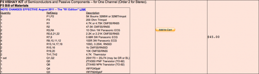
If you are keeping an eye on cost, the TechDIY kits are a very good deal, you will not save anything trying to source from other places, and you will probably get fake Jfets.
Buy an Antek 400VA transformer, don't get a 600 like I did. Also, the AN- series is the unshielded, and cheaper. So look for the AN-4218.
The 'standard' Pass PSU is a 18v+18v transformer with at least 60,000uf of capatance per rail. (120,000uf total) The Hafler schematic you posted is not necessarily wrong... but there are much better ways of doing it.
Also, define 'huge' when you are talking about your heatsinks. (I.E., how big are they exactly?) 'Huge', when talking about a class-A amp, are heatsinks measured in square feet.
Lastly, I would like to take this time to say Hello! and Welcome! This is a fantastically fun project, and we are very glad to see another guy deciding to build one. You will find lots of help here, just ask.
http://www.diyaudio.com/forums/pass-labs/188691-illustrated-guide-building-f5.html
Then read this at least twice, preferably more - http://www.firstwatt.com/pdf/prod_f5_man.pdf
If you are keeping an eye on cost, the TechDIY kits are a very good deal, you will not save anything trying to source from other places, and you will probably get fake Jfets.
Buy an Antek 400VA transformer, don't get a 600 like I did. Also, the AN- series is the unshielded, and cheaper. So look for the AN-4218.
The 'standard' Pass PSU is a 18v+18v transformer with at least 60,000uf of capatance per rail. (120,000uf total) The Hafler schematic you posted is not necessarily wrong... but there are much better ways of doing it.
Also, define 'huge' when you are talking about your heatsinks. (I.E., how big are they exactly?) 'Huge', when talking about a class-A amp, are heatsinks measured in square feet.
Lastly, I would like to take this time to say Hello! and Welcome! This is a fantastically fun project, and we are very glad to see another guy deciding to build one. You will find lots of help here, just ask.
Last edited:
This thread covers an awful lot of your questions --
http://www.diyaudio.com/forums/pass-labs/188691-illustrated-guide-building-f5.html
Then read this at least twice, preferably more - http://www.firstwatt.com/pdf/prod_f5_man.pdf
If you are keeping an eye on cost, the TechDIY kits are a very good deal, you will not save anything trying to source from other places, and you will probably get fake Jfets.
Buy an Antek 400VA transformer, don't get a 600 like I did. Also, the AN- series is the unshielded, and cheaper. So look for the AN-4218.
The 'standard' Pass PSU is a 18v+18v transformer with at least 60,000uf of capatance per rail. (120,000uf total) The Hafler schematic you posted is not necessarily wrong... but there are much better ways of doing it.
Also, define 'huge' when you are talking about your heatsinks. (I.E., how big are they exactly?) 'Huge', when talking about a class-A amp, are heatsinks measured in square feet.
Lastly, I would like to take this time to say Hello! and Welcome! This is a fantastically fun project, and we are very glad to see another guy deciding to build one. You will find lots of help here, just ask.
Nice thread with lots of pictures.
From what it looks like, you have a dual mono power supply. As far as grounding, it looks like I can use the Hafler power supply method, and Hafler type of grounding.
Correct me if I'm wrong though. I'm better at repairing things than building.
This is the transformer that I will use
https://www.antekinc.com/details.php?p=75
The heatsinks are from a Yamaha RX-V990, I will get the measurements later..
Attached is what I will buy for the boards. I understand these have all the components to install onto the boards I bought.... One kit per board though.
Three of these filter caps per rail would work (in parallel)
Digi-Key - 565-3329-ND (Manufacturer - E36D630HPN223MC67M)
Or is there a cheaper alternative? They can be snap in or whatever, This is going to be a rough build that works, until I can get a better chassis, and have more funds to build the amp into a pretty chassis.
Thanks for all the help so far guys. I really appreciate your time, and knowledge.
Attachments
Hi ouimetnick,
I just got my F5 running last weekend as a breadboard setup. I've probably got 15-20 hours on it so far. It was rather harsh and shrill for the first few hours but I ran it for 8-10 hours yeasterday and it really started to settle in. I used Toshiba power FETs and a 400VA transformer with cviller boards. The power supply is all DIY on a perf board. You should enjoy yours when it's running.
Have fun and good luck,
John
They should not sound harsh, period.
A lot though depends on the rest of your system, and what it is.
The term is GIGO (garbage in, garbage out).
Check and adjust ur bias point. That effects the overall sound.
Also the power supply will have a significant effect on what you hear. Urs looks basic, things like the bridges and the way you do the filtering will effect what comes out the other end. Even the brand of power resistors used on the board seem to have an effect.
_-_-bear
ouimetnick,
If you build dual mono, there is no grounding scheme that needs to be followed, EXCEPT how you ground the chassis. The input jacks should be floating.
Short lead lengths are best, so pay attention to layout.
The parts kit will work ok.
If you read the threads you will see that some people prefer to NOT install the thermistor circuit. But to start you should probably build the stock circuit, with an eye to being sure you have enough heatsink so that the temperature rise when biased properly is not excessive (ie. they stay cool ENOUGH so that you can comfortably leave your hand on the heatsink after it has been on a few hours).
Of course to start off, build what you have and improve later as you go along, IF you think you want or need to.
Have fun with your build!
_-_-bear
It's not a dual mono supply. It's bipolar with a dual secondary transformer, and 2 bridges.
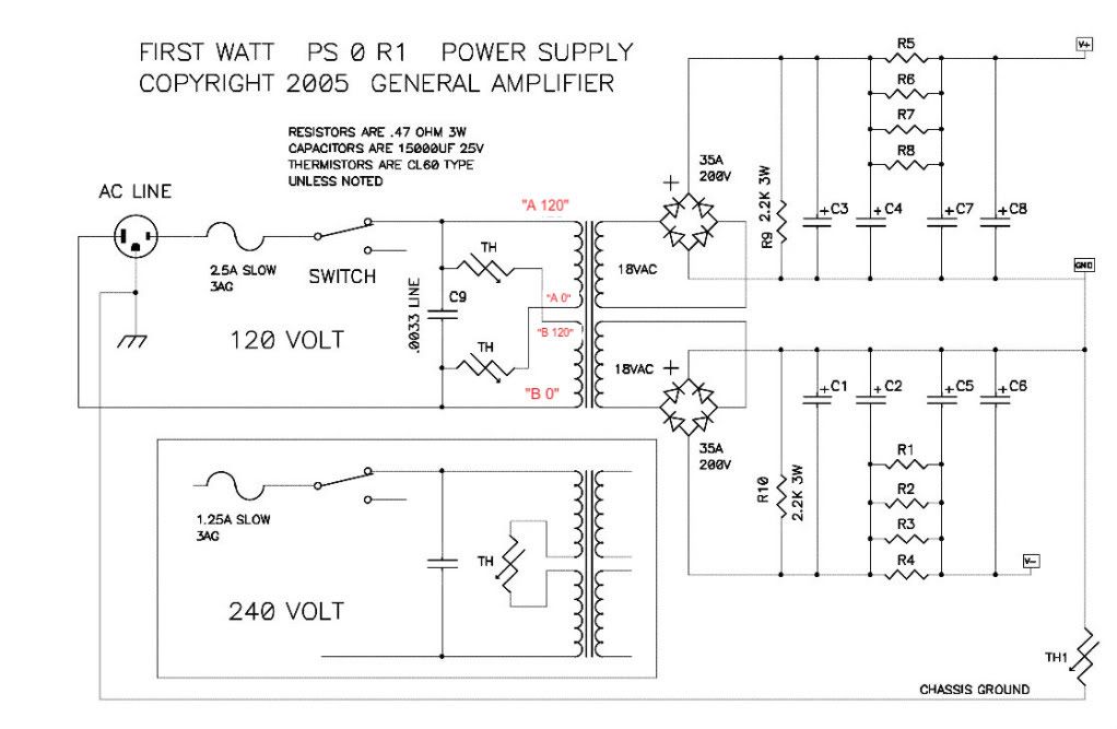
Since you are planning on using the Antek 4218 you really should make the supply like the above diagram.
The caps you chose will work, but you are paying extra $$ for the 63v rating which you don't need. PSU caps are expensive, you should get the right ones first.
There are a couple of circuit board options that work for the PSU. A proper board greatly simplifies the process and cuts way down on wiring errors.
Hi All,
I'm also a newbie about to purchase and build an F5
For the PS when using in Europe with220V mains, should C9 be .0033uf\250V ?
Can you recomend type and brands of resistors for the PS?
I'll be using the F5 with a B1 pre. Can anyone please recomend type and brands of caps at the input of the amp to avoid DC going to speakers?
Thanks you
IK
- Status
- This old topic is closed. If you want to reopen this topic, contact a moderator using the "Report Post" button.
- Home
- Amplifiers
- Pass Labs
- Yup. I'm building an F5! Here are my questions