IEC AC entry/fuse module
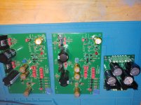
I finally got my act together and stuff the PCBs (see attached.) I have an Antek AS-0522 - 50VA 22V Transformer in route, as well as two Galaxy 2U enclosures.
Doing things in reverse, I am building a Mouser order for the PSU. This includes:
XLR Connectors 3P FEM BLACK/SILVER DUPLEX GRD CONTACT 568-NC3FD-LX-BAG
XLR Connectors 3P MALE BLACK/SILVR DUPLEX GRD CONTACT 568-NC3MD-LX-BAG
RCA Phono Connectors RCA PANEL JACK GOLD/WHITE REAN 568-NYS367-9
RCA Phono Connectors RCA PANEL JACK GOLD/RED REAN 568-NYS367-2
Bridge Rectifiers 35A 600V 583-MP356 (they are out of the 200V)
However, I am not sure what AC entry/fuse module to purchase. I am grateful for the help so far. Any advice on the AC entry module would be much appreciated.
Thanks,
Attachments
For the AC module I used this one, Mouser-Nr.: 631FN2851006
Attachments
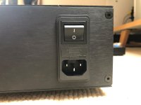
For the AC module I used this one, Mouser-Nr.: 631FN2851006
Excellent. Thank you!
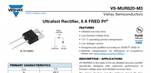
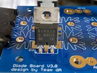
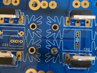
Stuffing MUR820 Diodes Help!
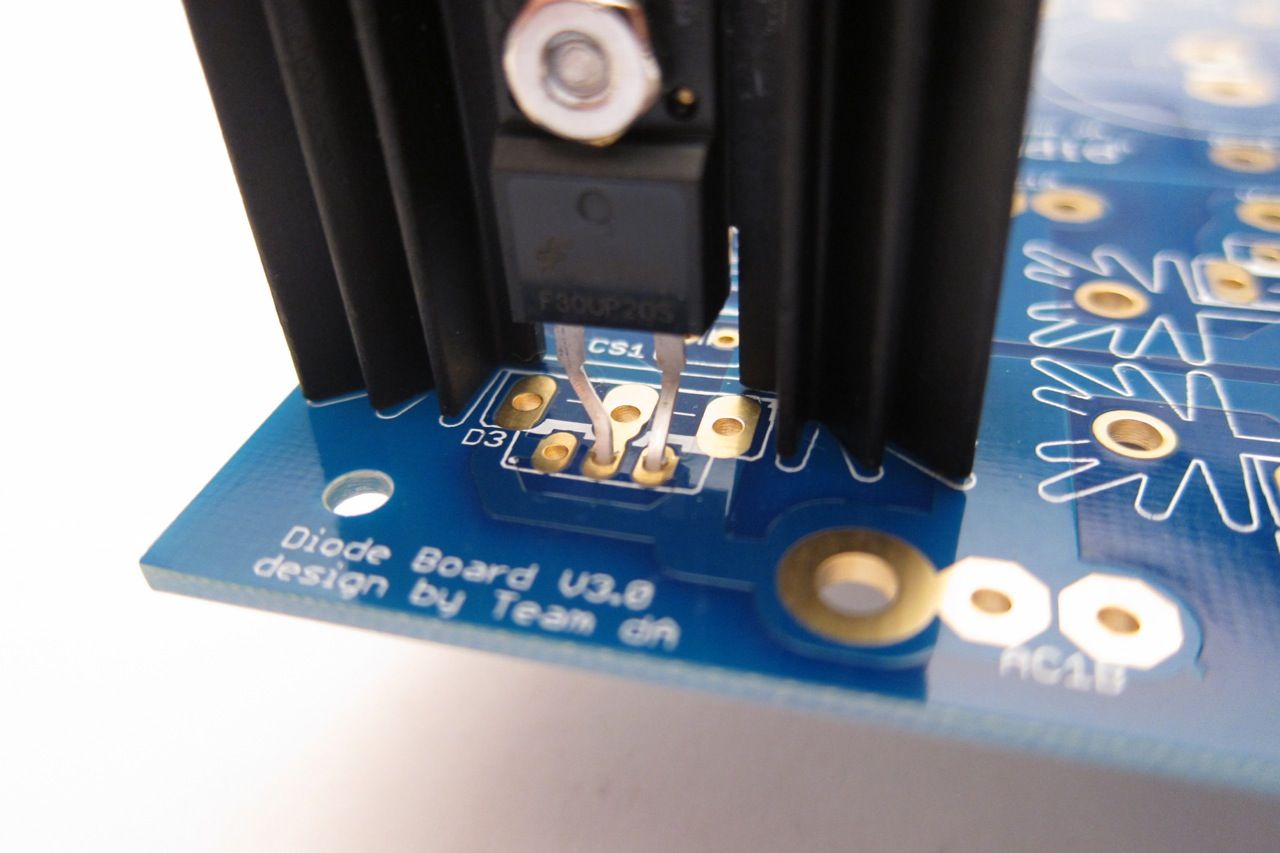
In the photo in your post the diodes are stuffed in an unconventional way - using alternate holes for the larger diodes, rather than the holes which fit a smaller TO220. Also there is a bridge to the smaller center hole? I've been searching for a pic of the diode boards stuffed with MUR820's and this is the closest i've seen!
Can i use the smaller set of pads for the MUR220 diodes and do i face base cathode towards the heat sink? These are two pin diodes in a three pin board so is that ok or how do i do this please help!
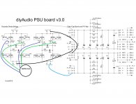
PS- ive seen the schematic, fwiw, a bit confusing in terms of understanding the current path on these boards.
From the wise advise of 6L6 I decided to swap my little standard diode bridges for some MUR820's I had laying around in the parts bin.
In the photo in your post the diodes are stuffed in an unconventional way - using alternate holes for the larger diodes, rather than the holes which fit a smaller TO220. Also there is a bridge to the smaller center hole? I've been searching for a pic of the diode boards stuffed with MUR820's and this is the closest i've seen!
Can i use the smaller set of pads for the MUR220 diodes and do i face base cathode towards the heat sink? These are two pin diodes in a three pin board so is that ok or how do i do this please help!
PS- ive seen the schematic, fwiw, a bit confusing in terms of understanding the current path on these boards.
Attachments
Hello all,
I am just about to start my first project, a Pearl 2 using a Universal Power Supply from the DIYAudio shop which I've already purchased. I am a total beginner, therefore, this project will be a significant challenge.
Thanks to all the members here and especially 6L6 for the tremendous build guides and contributions.
In the best traditions of DIY audio, I plan to over-specify the build I have some questions some of which have been raised before but I am not 100% clear and others are new for me, I would be grateful if the group can help me with my thinking.
1). The infamous snubber caps and resistors CX1, CX2, CS1, CS2, R11 and R12 - from my understanding of earlier posts although better to include but it is also possible to leave these parts out?
2). I plan to use 6,800uf 50v caps, 27,200 uf per rail - would it be okay to use 10,000uf, is there any benefit, the costs are similar.
3). I understand from posts by 6L6 that I should remove all the 0.47R 3 watt resistors and replace with 2, 10 ohm 3 watt resistors, one on each rail? Have I understood this correctly? Is one resistor enough or should I add another 0.47R 3 watt in parallel?
4). I have seen Pass labs and other members use filtered IEC inputs on some preamps, I am planning to use a Schaffner FN9290 (Mouser 631-FN9290-4-06) 4 amp dual stage filter or alternatively a Schaffner FN9280 (631-FN9280-4-06) 4 amp single stage both are combined IEC inlet, switch, fuse and filter, is there any benefit of the dual stage over the single stage and should I be ordering the 2amp version instead of the 4 amp version?
5). From Wayne’s schematic, I need to add a noise suppression cap of 0.0033uf before the transformer, since I plan to use a Schaffer filter above is the suppression cap still required? If it is required, will this Kemet work Mouser ref: 80-PME271M433MR30?
6). The 200v bridge rectifier diode block (Vishay GBPC3502-E4/51) is out of stock at both Mouser and Digikey, I plan to use the same Vishay diode block but in a 400v version (GBPC3504-E4/51), any problems here?
7). Primary earth, grounding hardware to the chassis, can I use any nuts, bolts and washers that I can get hold off or is there a set of parts I can buy in a kit for these.
My plan is to get the power supply up and running first and then tackle the Pearl 2 Boards later.
Thanks in advance for your support!
Power supply output polarity reversed
Hi All,
I finished wiring the PS for the pearl II today and it passed the dim bulb test. It outputs steady +/-30.5v at the outputs but the polarity is reversed? On what should be the positive rail i get -30v and vice versa.
Here's a couple pics if anyone can have a look at the wiring i would greatly appreciate it. All connections were from schematic, The CRCRC are 6800uf and .47ohm; Diodes MUR820's, snubber .22uf.
I don't want to blow up any caps should i be worried?
Attachments
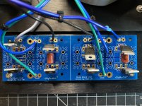
I traced all your wiring and everything looks as it should if you're expecting gray to be positive and blue to be negative, but you're getting the opposite. Are you sure your diodes aren't in backwards?
Also, with the readings you're getting it seems you would have blew a rocket by now.
Also, with the readings you're getting it seems you would have blew a rocket by now.
Last edited:
Disconnect the output of the diodes from the capacitors and power up with the dim bulb tester and measure your voltages out of the diode bridges.
Thanks for the advise, i should have checked it first. I'll post results and some pics tomorrow.
Greenwich -
1) The snubber values are not universal, but instead need to be computed for your specific transformer. Leave empty.
2) Use the 6800uF as you are planning.
3) One 10ohm 3W resistor per rail. Nothing more.
4) Either. Will both work very nicely, those are excellent mains inlets.
5) That cap, being “X2” rated, is suitable for the application. It is, however, superfluous since you are using the filtered mains inlet, so do not use.
6) As the bridge is required to carry mains faults to earth, you need one with a voltage at least that of the mains — get the 400V
7) Whatever will work. If you can get a star washer or two, to help dig into the chassis metal as well as hold everyting snug. Internal or external teeth, either will work.
Last edited:
Unless it's something simple (test leads reversed) I'd be worried.

Yes, i found the problem - the dmm leads were reversed. I managed to wire the whole thing correctly and then not figure that out ..
So i now have a Darwin award and a working power supply. Thanks all for your help and advise.

Last edited:
- Home
- Amplifiers
- Pass Labs
- Building a Pearl 2