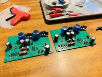
Wrapped up my Pearl 2 boards this evening. PSU is also ready - just waiting on chassis’ to arrive from Modushop. Pretty straightforward build so far. My goal was to get the RIAA boards in a 1U chassis, so that drove some of the component choices.
For the 6.81k resistor just before the RIAA portion, I used a couple Shinkoh resistors that measured in at 6.78k. Anybody see a potential problem in that 300R drop?
For the 6.81k resistor just before the RIAA portion, I used a couple Shinkoh resistors that measured in at 6.78k. Anybody see a potential problem in that 300R drop?
Attachments
Hello members,
I use exactly the same bridge-rectifier together with a CL-60 thermistor for
building my ground-loop-breakers.
I use them in all of my DIY- Pass-poweramps.
Sometimes I did it with 2 single Diodes (direction against each other - paralleled together with a paralleled resistor around 10 Ohms) in my preamps, active crossovers,... with lower power consumption.
Works beautiful. Also in Germany with 230V/50Hz.
But hum or hiss can also have other reasons!
But often there are groundloops. My experience.
Greets
Dirk
what does CL-60 mean? i am about to complete an order for a few parts and im inclusing the ones for the ground loop breaker and the last parts that im not sure about which speciufications to buy is the thermistor.
im getting this rectifier: GBPC3510 ON Semiconductor / Fairchild | Mouser
If not, get shorter brass standoffs.Wrapped up my Pearl 2 boards this evening. PSU is also ready - just waiting on chassis’ to arrive from Modushop. Pretty straightforward build so far. My goal was to get the RIAA boards in a 1U chassis, so that drove some of the component choices.
For the 6.81k resistor just before the RIAA portion, I used a couple Shinkoh resistors that measured in at 6.78k. Anybody see a potential problem in that 300R drop?
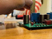
What size are the RIAA PCB's?
This was asked at Post #10 but no answer was given as far as I can see. Spent a couple of hours looking for this info as its not on the passdiy.com pages.
If you print out the board layout from page 5 of Wayne's build guide with no page scaling, the size will be very close to the actual board, within a few millimeters. On your printout, the lead spacing for C1 and C26 (10000 mfd) should measure 10mm and the regulator heat sink mounting pin spacing should equal 25.4mm
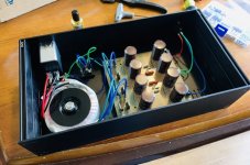
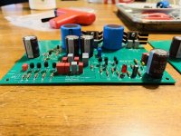
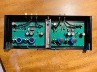
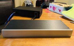
Finally wrapped up my Pearl 2 last weekend. What a phenomenal phonostage! Huge thanks to 6L6 for your help, and to Wayne for the superb design.
Pictured are shots of the PSU (in Galaxy case) and the RIAA (in 1U slimline case.) Had 2mm to spare!
Pictured are shots of the PSU (in Galaxy case) and the RIAA (in 1U slimline case.) Had 2mm to spare!
Attachments

@codyt - Very tidy wiring scheme, less chance of picking up noise. I wanted the board sizes so I could plan my own layout. I will be taking tips from yours for sure. Well done.
I mounted mine with one board rotated 90 degrees counter clockwise to keep the twisted pair input wires as short as possible hoping it would reduce the possibility of picking up noise. It is dead quiet.
")
I built an Elekit TU-8500 preamp for a friend and it has an onboard opamp-based phono stage. As a whole the unit sounds excellent, but when I turn up the volume on the phono stage all I hear is hissssssssssss. If I wasn't used to the Pearl 2's silence, I probably wouldn't have even noticed it.
Pass DIY Addict
Joined 2000
Paid Member
I mounted mine with one board rotated 90 degrees counter clockwise to keep the twisted pair input wires as short as possible hoping it would reduce the possibility of picking up noise. It is dead quiet.
I'll look at that arrangement as well.
I have a plan view photograph of the PCB. I cropped it to the board edges in Coral Paint and then using Coral Draw, scaled it to 1:1. I set the work sheet to A3 size, imported all the main components using this method and will move them around till I find a layout that works best for the wiring. I will only look for a case, when I know what the layout will be.
What do folks do about adjustments, cartridge loading etc.
I noticed one build, with dip switches on the back panel to select resistance/capacitance. Are others building to set values that suit their cartridge of choice?
I only use LOMC cartridges with an output between 0.3 and 0.5mV, 55dB may not be enough?
I believe the gain required for a 0.5mV cartridge to produce 1V Phono stage output is 66dB. 0.3mV requires 70.5dB for 1V output.
The rest of the gain chain will effect things of course, but what Phono gain level are folks using, for cartridges with this level of output?
I'm weighing up 55dB v 65dB and the possibility of additional noise at 65dB. I would rather have a fixed gain, than two or three settings and a switch.
Any feedback on this subject would be appreciated.
I have cartridges in that mV range and use the high gain config of the Pearl 2 with R14 at 300 ohms. This into a BA-3 and F5, and I have more than enough gain. I also put rotary switches on the front to control gain and loading. I wouldn't worry about noise at the high gain setting.
I’m using my Pearl 2 with an MM cart and can afford to throw away some gain. My first stage jfets measure 54mV at the source resistors, up 14mV from the suggested 10-40 range. I’m wondering if a gain reduction would make more sense with an adjustment to the first stage source resistors instead of at R14? If I follow this logic, any suggestions on what I change the source resistor values to?
- Home
- Amplifiers
- Pass Labs
- Building a Pearl 2