Pass DIY Addict
Joined 2000
Paid Member
Thanks Mark & BK. I was undecided about using the LED at all, so I didn't want to drill a separate hole for it. This is the switch that I used:
16mm Latching Push Button Power Switch Stainless Steel w/ Blue LED Waterproof | eBay
I figured if I didn't like the LED, I could disconnect its power supply and it would just look like a push button switch.
16mm Latching Push Button Power Switch Stainless Steel w/ Blue LED Waterproof | eBay
I figured if I didn't like the LED, I could disconnect its power supply and it would just look like a push button switch.
Thanks Mark & BK. I was undecided about using the LED at all, so I didn't want to drill a separate hole for it. This is the switch that I used:
16mm Latching Push Button Power Switch Stainless Steel w/ Blue LED Waterproof | eBay
I figured if I didn't like the LED, I could disconnect its power supply and it would just look like a push button switch.
Where are you sourcing 12vdc for the LED?
Pass DIY Addict
Joined 2000
Paid Member
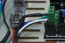
I used the AC secondary going into the regulator - I didn't want to pollute the nice regulated DC that feeds the Pearl boards. I added whatever 1N4004-like diode was in my box on one leg followed by a 20k (adjust brightness to taste) resistor. Diode first, then resistor, then LED. Both are wrapped in heat shrink. The other leg just returns to the other end of the secondary.
I've attached a cropped image - it's a bit grainy though because this was not the focal point of the original image. The green & blue are the standard Antek secondary, the white and black power the LED. Technically, the LED is blinking at 60Hz, but I can't see that fast") . If your AC supply is higher, just use a larger resistor. You could drive it right from the 120v mains if you want with the same arrangement, just pick a 100k-150k resistor...
. If your AC supply is higher, just use a larger resistor. You could drive it right from the 120v mains if you want with the same arrangement, just pick a 100k-150k resistor...
I've attached a cropped image - it's a bit grainy though because this was not the focal point of the original image. The green & blue are the standard Antek secondary, the white and black power the LED. Technically, the LED is blinking at 60Hz, but I can't see that fast
. If your AC supply is higher, just use a larger resistor. You could drive it right from the 120v mains if you want with the same arrangement, just pick a 100k-150k resistor...Attachments
Last edited:
I used the AC secondary going into the regulator - I didn't want to pollute the nice regulated DC that feeds the Pearl boards. I added whatever 1N4004-like diode was in my box on one leg followed by a 20k (adjust brightness to taste) resistor. Both are wrapped in heat shrink. The other leg just returns to the other end of the secondary.
I've attached a cropped image - it's a bit grainy though because this was not the focal point of the original image. The green & blue are the standard Antek secondary, the white and black power the LED.
Very nice, I think I'll order a couple of these to class up my rig.
Pass DIY Addict
Joined 2000
Paid Member
Ha- I'm still wondering if I should have chosen the black push button switch to match the screws I used and better fit the wood grain... We all have too much OCD
If you want to order a black one I'll buy the silver from you. I think it would look better matching the screws.
That's the one specified in the Pearl 2 doc.
I have an extra one that I just posted in the Swap Meet.
I have now started my (re)build of the Pearl Two on the official boards. I noticed a strange thing: at the ground side of R7 the solder pad seemed to reject the solder (on both sides of the board). This was the same in both boards. No problems elsewhere on the boards so far (I've only done a few resistors). I'm using 60/40 solder that has never given me problems before. Has anyone else encountered something like this before? I'm a bit worried about the quality of the connection, time will tell when the boards are finished.
Tip touching the lead and the PCB at the same time, feed a little solder into the joint, when the surface tension of the solder changes and it 'sucks into' the hole because everything is the same temperature, you're good.
This is more of a time issue than overall temperature.
This is more of a time issue than overall temperature.
Need a bit of help Guys..
Built a Pearl II quite some time ago Apr 2017ish. My issue is the P1 0 volts. I could never obtain a steady state 0v rather it would float from - to +mV as much as 100 in both directions but from time to time would hold a steady + - 10mV but over a period of say 10 minutes it would go off on one but would come back to 0 then off in the other direction.....
Now I have a P1 of 4.0volts + . Which sets up a horrid crackling while listening. DC on the out is less than 10mV at this time.
I can tweak P1 back via the 5K pot but over long periods (many months) it creeps up again. (well its done it twice now) As the P1 0v move up the sound degrades so I know what to expect.
TIA
Attachments
Last edited:
You can solve this by inserting an electrolytic cap between R14 and ground (47-470 uF), many have done that. I believe bypassed with a small film cap of 0.1 uF or something like that. Search this thread and the Pearl Two thread. On a previous build I put an Elna Silmic II of 100uF in there and the DC was stable at 0V. At the moment I'm rebuilding the Pearl on the official boards. I will try without the cap first, but might go this route id DC is not stable within reasonable margins.
Pass DIY Addict
Joined 2000
Paid Member
Here is what Wayne had to say about adding a cap to reduce offset drift (I don't have the direct link, but it's in this thread somewhere). I did this and it worked great, DC offset is now rock solid very close to 0.0mV.
"The cap in series with R14 (on the ground side, but being a series arrangement either way should work) keeps the DC gain at unity making the DC offset more stable. Use a nice (Silmic) electrolytic 47uF - 470uF works fine, 25v or more and use a film bypass if you want. Just lift the ground side of R14 and connect to the + lead of the cap and the - lead goes to ground. A bipolar cap would work here also but a standard electrolytic will work and they can take small amounts of reverse voltage but this shouldn't be a problem. If you get it all setup and adjusted you may not need output cap.
Leave P1 in it adjusts the DC offset. You can maybe remove the output coupling cap if you use the cap in series with R25. Short the cap out with a clip lead adjust P1 for the best you can get then remove the clip lead."
Edit: some of the discussion starts here: Building a Pearl 2
Last edited:
- Home
- Amplifiers
- Pass Labs
- Building a Pearl 2