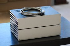
Finally had a chance to test out my Pearl 2 Build ... Lady Luck was with me and she played perfectly straight out of the gate  . Many of you will laugh at me, but I guess I need to go buy a good turntable now (borrowed a friends for testing purposes
  ).
).
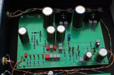
I built the gain boards stock except for adding a 220uF series capacitor to R14 to stabilize DC offset. The offset slowly and slightly wanders, but stays less than +/-1mV.
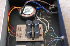
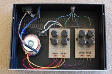
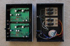
For the power supply I went dual mono after the transformer (24V secondaries), which was a minor mistake because I had originally designed around one supply for both channels, and after splitting it the voltage rails crept up to 35V leaving no safety margin for the caps on the gain boards in front of the regulators. Used CLC with 10,000uF caps and 6.8mH inductors that also had 14.7 ohm DCR (measured). I'm really happy with how the PS turned out, as it has ~0.2mV ripple, and will really keep RF down as well.
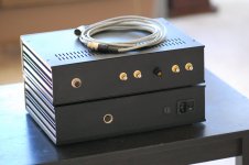
I was really concerned about hum from grounding and from the PS radiated noise, so I made my power umbilical 10ft long just to be safe. I definitely have avoided hum, its dead quiet except for a slight Mosfet hiss if I crank the volume up and put my ear right next to the speaker. For giggles I stacked the two chassis just to see what happens, and it stayed just as silent. Thank you to 6L6 and everyone else on their grounding layout advice.
The sound was excellent straight out of the gate with an entry level ProJect turntable and an Ortofon OM-5 cartridge. I'm curious to see what some burn in time will produce, and how it sounds with the Dual 505-3 that I inherited from my Dad but now need to pick up from my dear ol' Mum. My suspicion is that I will find myself bit by the upgrade bug wrt to the turntable.
. Many of you will laugh at me, but I guess I need to go buy a good turntable now (borrowed a friends for testing purposes ).I built the gain boards stock except for adding a 220uF series capacitor to R14 to stabilize DC offset. The offset slowly and slightly wanders, but stays less than +/-1mV.
For the power supply I went dual mono after the transformer (24V secondaries), which was a minor mistake because I had originally designed around one supply for both channels, and after splitting it the voltage rails crept up to 35V leaving no safety margin for the caps on the gain boards in front of the regulators. Used CLC with 10,000uF caps and 6.8mH inductors that also had 14.7 ohm DCR (measured). I'm really happy with how the PS turned out, as it has ~0.2mV ripple, and will really keep RF down as well.
I was really concerned about hum from grounding and from the PS radiated noise, so I made my power umbilical 10ft long just to be safe. I definitely have avoided hum, its dead quiet except for a slight Mosfet hiss if I crank the volume up and put my ear right next to the speaker. For giggles I stacked the two chassis just to see what happens, and it stayed just as silent. Thank you to 6L6 and everyone else on their grounding layout advice.
The sound was excellent straight out of the gate with an entry level ProJect turntable and an Ortofon OM-5 cartridge. I'm curious to see what some burn in time will produce, and how it sounds with the Dual 505-3 that I inherited from my Dad but now need to pick up from my dear ol' Mum. My suspicion is that I will find myself bit by the upgrade bug wrt to the turntable.
Attachments
-
 Pearl Both Front.jpg812.2 KB · Views: 692
 -
 Pearl PS Board.jpg862.9 KB · Views: 337
 -
 Pearl PS Overview.jpg738.7 KB · Views: 353
 -
 Pearl Gain Board.jpg941 KB · Views: 556
 -
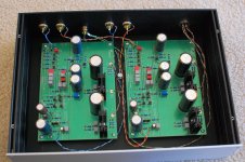 Pearl Gain Overview.jpg782.6 KB · Views: 689
 -
 Pearl Both Inside.jpg821.3 KB · Views: 693
 -
 Pearl Both Back.jpg819.6 KB · Views: 688
Last edited:
New Pearl 2 - too sensitive
Hi all, just finished my second Pearl 2. Voltages check out OK, the LEDs light up, offset is set near zero. Both boards are super-sensitive and loud, especially with MM cartridges. They distort on loud passages but sound fantastic otherwise. With my O2 headphone amp I can't turn the volume past 7 or 8 o'clock.
R14 checks out at 1K. Any ideas what's going on?
Finally had a chance to test out my Pearl 2 Build ... Lady Luck was with me and she played perfectly straight out of the gate
Congrats, that's a very nice looking build. Love to hear it sometime.
jeff
The Pearl 2 is designed to be used with low output MC cartridges, you will be severely overloading it with a high output MM cartridge. IIRC the Pearl 1 was designed for MM cartridges.
It would be counter advantage to have the extra gain of the Pearl 2 to then attenuate it as the Pearl 2 by its nature will be noisier than a Pearl 1.
It would be counter advantage to have the extra gain of the Pearl 2 to then attenuate it as the Pearl 2 by its nature will be noisier than a Pearl 1.
Last edited:
The Pearl 2 is designed to be used with low output MC cartridges, you will be severely overloading it with a high output MM cartridge. IIRC the Pearl 1 was designed for MM cartridges.
The Pearl 2 default is 55db of gain for MM carts, reducing R14 to 300 ohm increases it to 65db for MC carts. I've been using a Pearl 2 for a long time with both.
I use mine with a low output Linn Aktiv and it performs perfectly. My point is that the OP is clearly over driving his.
I'm trying to figure out how it's being overdriven by a 4mv cartridge - this is my second Pearl 2, and the first one has no issues with the same cart. There is something going on with it.
Yep, Jack suggested a 100k resistor in the Cx position and this solved the problem for me.
I've now built a BA-3 preamp with a volume control before the BA-3 boards, so it doesn't matter any more. I actually forgot the 100k was in place
On another topics, I presume it is OK to parallel a second set of RCAs on the back of my Pearl if I separate them from the first set of RCAs with a ~100R resistor. Would this cause any problems that I am not thinking about?
This looks promising...
Here's the new build BTW!
Edit - was going to mention that the connections to the rotary switches are Belden microphone cable, with all the drain wires going back to the input ground. Once that was done it got nice and quiet. It has 3 gain settings, 5 resistive load settings and 5 capacitive settings including zero.


Edit - was going to mention that the connections to the rotary switches are Belden microphone cable, with all the drain wires going back to the input ground. Once that was done it got nice and quiet. It has 3 gain settings, 5 resistive load settings and 5 capacitive settings including zero.
Last edited:
This looks promising...
Well adding 100K to Cx seems to have done the trick. Apparently the output of the P2 was overdriving the preamp. I wonder if increasing R14 to something over 1K would do the same thing?
@KatieandDad I saw your build and system, very nice.
Pass DIY Addict
Joined 2000
Paid Member
I use an Audio Technica 5mV MM cartridge which initially caused distortion for me as well. There are two solutions- I had to implement both to make my distortion go away:
First Gain Stage:
Change R21 through R24 from 10R to 20R. This reduces the current through the first stage to about 5.3mA.
Second Gain Stage:
Parallel R16 (100k) with resistor in Cx location can alter the gain for high output MM cartridges.
Approximate resulting second stage gain for net values of feedback
R16 originally 100k, Cx originally open:
150k (replace R16 with 150k, Cx = empty) about 43,5dB (increases output by 3.5dB)
100k (Cx = empty) about 40dB gain (original output level, R16=100k)
66k (Cx=200k) about 36dB gain (decreases output by 4dB)
50k (Cx=100k) about 34dB gain (decreases output by 6dB)
33k (Cx=50k) about 30dB gain (decreases output by 10dB)
Hope this helps!
I use an Audio Technica 5mV MM cartridge which initially caused distortion for me as well. There are two solutions- I had to implement both to make my distortion go away:
First Gain Stage:
Change R21 through R24 from 10R to 20R. This reduces the current through the first stage to about 5.3mA.
The first gain stage isn't the problem, and reducing it means that the signal at the end of the passive network is less than it was going in!
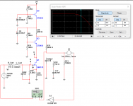
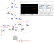
One easy way of reducing distortion in higher output MM cartridges is to get the inductance from the data sheet. With this you can lower the value of "R19" from 47k5 to create a pole ahead of the RIAA network. It requires a bit of tweaking to get a flat response, but not difficult:
Attachments
I use an Audio Technica 5mV MM cartridge which initially caused distortion for me as well. There are two solutions- I had to implement both to make my distortion go away:
First Gain Stage:
Change R21 through R24 from 10R to 20R. This reduces the current through the first stage to about 5.3mA.
Second Gain Stage:
Parallel R16 (100k) with resistor in Cx location can alter the gain for high output MM cartridges.
Approximate resulting second stage gain for net values of feedback
R16 originally 100k, Cx originally open:
150k (replace R16 with 150k, Cx = empty) about 43,5dB (increases output by 3.5dB)
100k (Cx = empty) about 40dB gain (original output level, R16=100k)
66k (Cx=200k) about 36dB gain (decreases output by 4dB)
50k (Cx=100k) about 34dB gain (decreases output by 6dB)
33k (Cx=50k) about 30dB gain (decreases output by 10dB)
Hope this helps!
Yes that's very helpful. If I do a quick resistors in parallel calculation, the 2 x100K I have in place is about equivalent to your 66k+200k.
I was listening last night with a 5mv Signet TK7LCa (super bright but I like it) and while the gain is still high, my preamp wasn't having any issues.
Not sure why some Pearl 2s have a lot more gain than others - is it due to variances in the JFETs?
One thing about this build that is bothering me is while the 7824 regulator is putting out 23.98v, the 7924 is putting out 23.67. I verified that exactly +28 and -28v are going in from the PS.
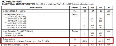
Check your PCB to find out which semiconductor company made the 7924 regulator IC on your board. Then pull up the manufacturer's datasheet. I've attached a piece of the datasheet from ON Semiconductor below; yours may be formatted slightly differently.
The red box shows a guarantee that ON Semiconductor makes to its customers. Every single MC7924, no matter what temperature, no matter what output current, is guaranteed to deliver a regulated output voltage between -22.8 volts and -25.2 volts. It could be anywhere in that range. Some units that roll off the manufacturing line will be towards the lower end of the range, and other units will be towards the upper end of the range. (They follow a bell shaped curve, the so called Gaussian Distribution).
Wayne Colburn knew this when he designed the Pearl-2. It won't surprise him at all to hear that your 7924 voltage regulator's output is -23.67 volts ; after all, -23.67 is between -22.8 and -25.2. ON Semi met its guarantee. Don't worry, be happy.
Oh by the way, the guaranteed limits (-22.8V and -25.2V) happen to be 5% below, and 5% above, the -24V target. Is this a numerical accident? Oh no.
_
Attachments
Last edited:
Check your PCB to find out which semiconductor company made the 7924 regulator IC on your board. Then pull up the manufacturer's datasheet. I've attached a piece of the datasheet from ON Semiconductor below; yours may be formatted slightly differently.
The red box shows a guarantee that ON Semiconductor makes to its customers. Every single MC7924, no matter what temperature, no matter what output current, is guaranteed to deliver a regulated output voltage between -22.8 volts and -25.2 volts. It could be anywhere in that range. Some units that roll off the manufacturing line will be towards the lower end of the range, and other units will be towards the upper end of the range. (They follow a bell shaped curve, the so called Gaussian Distribution).
Wayne Colburn knew this when he designed the Pearl-2. It won't surprise him at all to hear that your 7924 voltage regulator's output is -23.67 volts ; after all, -23.67 is between -22.8 and -25.2. ON Semi met its guarantee. Don't worry, be happy.
Oh by the way, the guaranteed limits (-22.8V and -25.2V) happen to be 5% below, and 5% above, the -24V target. Is this a numerical accident? Oh no.
_
Good to know, thanks! I am using the ON MC7924CTG.
I use an Audio Technica 5mV MM cartridge which initially caused distortion for me as well. There are two solutions- I had to implement both to make my distortion go away:
First Gain Stage:
Change R21 through R24 from 10R to 20R. This reduces the current through the first stage to about 5.3mA.
Second Gain Stage:
Parallel R16 (100k) with resistor in Cx location can alter the gain for high output MM cartridges.
Approximate resulting second stage gain for net values of feedback
R16 originally 100k, Cx originally open:
150k (replace R16 with 150k, Cx = empty) about 43,5dB (increases output by 3.5dB)
100k (Cx = empty) about 40dB gain (original output level, R16=100k)
66k (Cx=200k) about 36dB gain (decreases output by 4dB)
50k (Cx=100k) about 34dB gain (decreases output by 6dB)
33k (Cx=50k) about 30dB gain (decreases output by 10dB)
Hope this helps!
Question -- since gain is controlled by changing R14 between 1K and 300R, why not increase R14 to 1.5K or so instead of changing R16?
Pass DIY Addict
Joined 2000
Paid Member
There are several resistors that work in combination to alter gain. Soldering some female sockets into the Cx location provided the easiest way to experiment with different values with a minimum of soldering, so this is the path I chose. I saw in the pearl thread that you installed a switch on R14. This is a more flexible solution once the experiment is over. I like your build very much!
Perhaps it's time to go back and experiment again with resistor values. That, or just get a MC cartridge...
Perhaps it's time to go back and experiment again with resistor values. That, or just get a MC cartridge...
I’ve read the two Pearl 2 threads a couple of times over, and I’m still trying to wrap my head around this issue of high frequency signals from higher output MM cartridges causing overloading of the Pearl 2 second gain stage. I ran the math and it isn’t adding up, or I’m doing the math wrong. So I’m throwing this out here for discussion and to be back-checked.
Jackinnj posted that the issue is at high frequencies a MM cartridge can output a signal up to 70mV (if I’m mis-quoting, please correct me). So I choose a 70mV signal at 10kHz to run my calcs.
The 1st gain stage is +35dB or 56.2X, making the output of the 1st stage 3.94V.
At the RIAA filter network:
C10,C11 and C14 make a composite capacitor of 0.12uF, which at 10kHz has Z=133R.
C17,C18,C19 and C20 make a composite capacitor of 0.333uF, which at 10kHz has Z=47.8R
C12 and C16 make a composite capacitor of 0.2uF, which at 10kHz has Z=79.8R
Then we also have R11=6.81k, R12=909R, and R13=100k.
I’m going to call the node connecting R11 and R12 “A” and the node connecting R13 to C12 and C16 “B”.
Between Node A and ground at 10kHz we have an impedance of:
(1/133 + 1/(909+47.8) + 1/(79.8+100k))^-1 = 116.6R
So that at Node A that signal is:
3.94V x (116.6/(116.6+6.81k)) = 0.066V
This is then divided again (negligibly) by C12, C16 and R13 to produce a signal at Node B of:
0.066V x (100k/(79.8+100k)) = 0.066V (still).
This signal at Node B then drives the 2nd gain stage which has a 40dB Gain or 100X. So the output of the 2nd Gain stage is 6.6V. Let’s assume, to be conservative, that it is an RMS level, so we then have a max signal level of 9.37V(peak).
Since the rails are ~+/-24V, and the output mosfet is conservatively dropping 4V from the rails, the output stage can handle swings of +/-20V, leaving us with some headroom available before clipping.
So, in summary, I’m confused! There has been some knowledgeable people here discussing this issue, who I’m very inclined to trust, but my calculations say we shouldn’t have an significant issue. So what am I missing?
Terry
- Home
- Amplifiers
- Pass Labs
- Building a Pearl 2