I know I'm late to the party now that everybody talking of P3, but I'm a proud owner of a P2 since about three month.
It's very silent (powered with @rhthatcher external power supply) and sound amazing
Some picture took before final assembly

It's very silent (powered with @rhthatcher external power supply) and sound amazing
Some picture took before final assembly
Attachments
I had a bit of an odd experience with my Pearl II and wondered if someone could shed some light, as I think it may be revealing a fault in one of the channels.
I connected the pearl II to my preamp using a set of Musiclink interconnects which are purported to have a RLC circuit between signal and ground inside a black box. What ended up happening was that I got a huge amount of hiss out of one channel of my phono stage with nothing connected. The other channel was silent. Any thoughts as to where to look? This has only been a problem with this set of cables, and changing the cables left for right didn't change anything.
I do recall we had a bit of a misfire when we built this preamp too, and left an LED out which caused a resistor to overheat. Not sure if that would possibly be related but those parts were obviously replaced and the stage works. I've always felt like there was a little channel imbalance but just chalked it up to my years of drumming with no headphones on. Now I'm not so sure.
Any input is appreciated as to a logical starting place.
Thanks!
This has only been a problem with this set of cables
Use different cables.
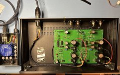
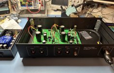
I know I'm late to the party now that everybody talking of P3, but I'm a proud owner of a P2 since about three month.
It's very silent (powered with @rhthatcher external power supply) and sound amazing
Some picture took before final assembly
View attachment 1244821
Mvaldes,
Where did you obtain the umbilical cord from? And would you be so kind as to point me to that external power supply that you mentioned above? Thank you so much.
That's gorgeous! Thanks for sharing.I know I'm late to the party now that everybody talking of P3, but I'm a proud owner of a P2 since about three month.
It's very silent (powered with @rhthatcher external power supply) and sound amazing
Some picture took before final assembly
May I ask how you did the graphics? Silkscreen?
You maybe able to find it at his shop: https://www.etsy.com/shop/ThatcherDIYAudioMvaldes,
Where did you obtain the umbilical cord from? And would you be so kind as to point me to that external power supply that you mentioned above? Thank you so much.
Lots of goodies.
I made the umbilical cord by myself with 3x16 AWG wire, a Copper Braided shielding sheath, and a braided sleeveMvaldes,
Where did you obtain the umbilical cord from? And would you be so kind as to point me to that external power supply that you mentioned above? Thank you so much.
Connector is a Neutrick PowerCon and it's receptacle
I designed front and back panel and let Modushop made for me
Hello.I just made an updated Pearl power supply for the PassDIY Pearl Phono. The design goals for the board and power supply included:
It's now running on my Pearl 2, and I'll be shipping it in a few days for a long term beta tester.
- Compact with PCB mount transformer
- Able to fit in an off-the-shelf chassis (e.g. Hammond) OR into the 10x10 grid of a Modushop / DIYAudio chassis
- CRCRC filtering for each rail
- Include optional snubber circuitry
- Include ground break rectifier on the PCB
- Include A/C cap on the PCB
- Flexibility for 120/240 mains
- LEDs on PCB (for rail voltage indication and front panel indicator)
Rails are ~34V, with one a little higher than the other. I used the PCB fab house to make aluminum PCBs as front and back plates.
I plan to write up a Build Doc and BOM, then offer up the main PCB and front/back plate PCBs. Stay tuned. I have a few sets on hand, PM if interested.
I'm not a professional, but I need a power supply for PassDIY Pearl Phono2 and shortly also Pearl 3 in EU (AC 230 V in Poland). Could you send me private info?
Thanks, Peter
Hi, Anyone up for helping me out to determine some resistor values for different gain/feedback settings?
I have a pearl 2 I put together a while ago with fixed gain around 40db IIRC for MM use, eventually I'm going to try out some MC carts so I want to up the gain a little and while I'm at it, make it adjustable. I have got some really small SPDT switches that fits nicely on the pcb so that it is possible to have two different values for R14-16.
Now my problem is this: I can not get my head around what the value on those resistors should be, ideally and if possible I want 5 db or so steps from say 30-35 to 65db, so thinking of maybe make R15-16 into 4 steps with 5db apart and use R14 as a hi/lo setting.
I have been searching this thread, and indeed find some relevant posts, but I'm still struggling to figure out what the values should be to make it as "adjustable as possible" in my case.
Thanks, but I really want to try out the spdt switches as they would make possible a very neat way to switch between two values in each spot without running any wire or longer leads, only compromise being a few more switched connections in the feedback loop, but with high quality spdt switches I think this should be OK.
I will for once provide pictures when done if it turns out as I hope as it dosent seems to meny people have opted for this solution and I think some might find it a good way to add some easy enough flexibility for gain settings without running feedback path "too far" off board
I will for once provide pictures when done if it turns out as I hope as it dosent seems to meny people have opted for this solution and I think some might find it a good way to add some easy enough flexibility for gain settings without running feedback path "too far" off board
I forget which post I got this from. It's somewhere earlier in this thread.
This is how I built my P2 with a 3 way toggle switch.
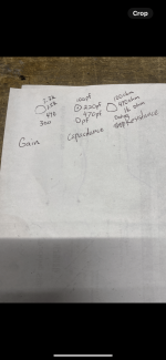
Here are other notes from my build on my PC. Maybe helpful for you.
Notes/Modifications
- Added Cap between R14 & ground
- RIAA EQ Optimization: R12 to 990 and C20 to 0.22 – See DIYAudio Pearl 2 Thread Post #1340
- C7 & C15: Empty
- R15: Jumper
Nice thanks! Exactly what I needed, think I can do calculations on my own with that info ")
I will check out those other mods you mention as well, although some might already be implemented the first time around, think I have to start taking some notes on these things, like you did 🤔
I will check out those other mods you mention as well, although some might already be implemented the first time around, think I have to start taking some notes on these things, like you did 🤔
- Home
- Amplifiers
- Pass Labs
- Building a Pearl 2